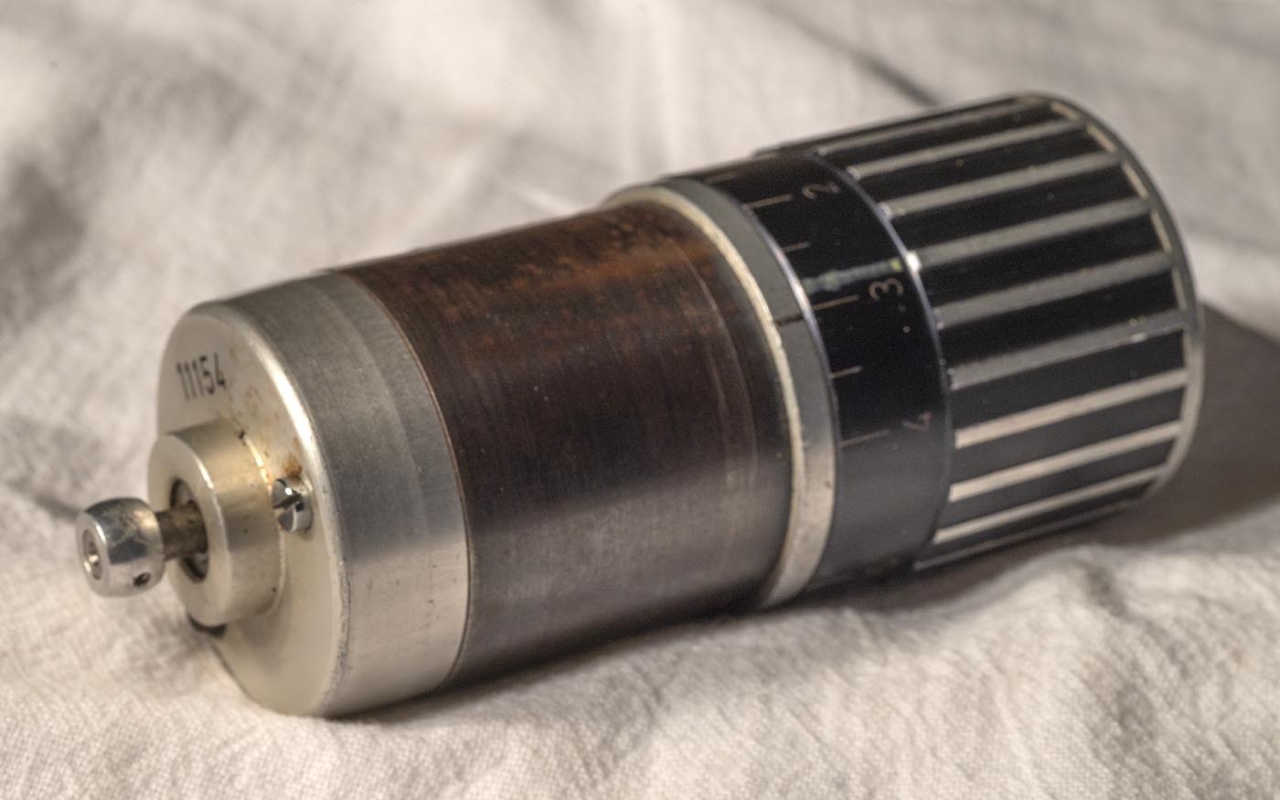
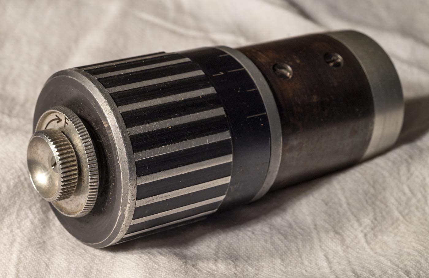
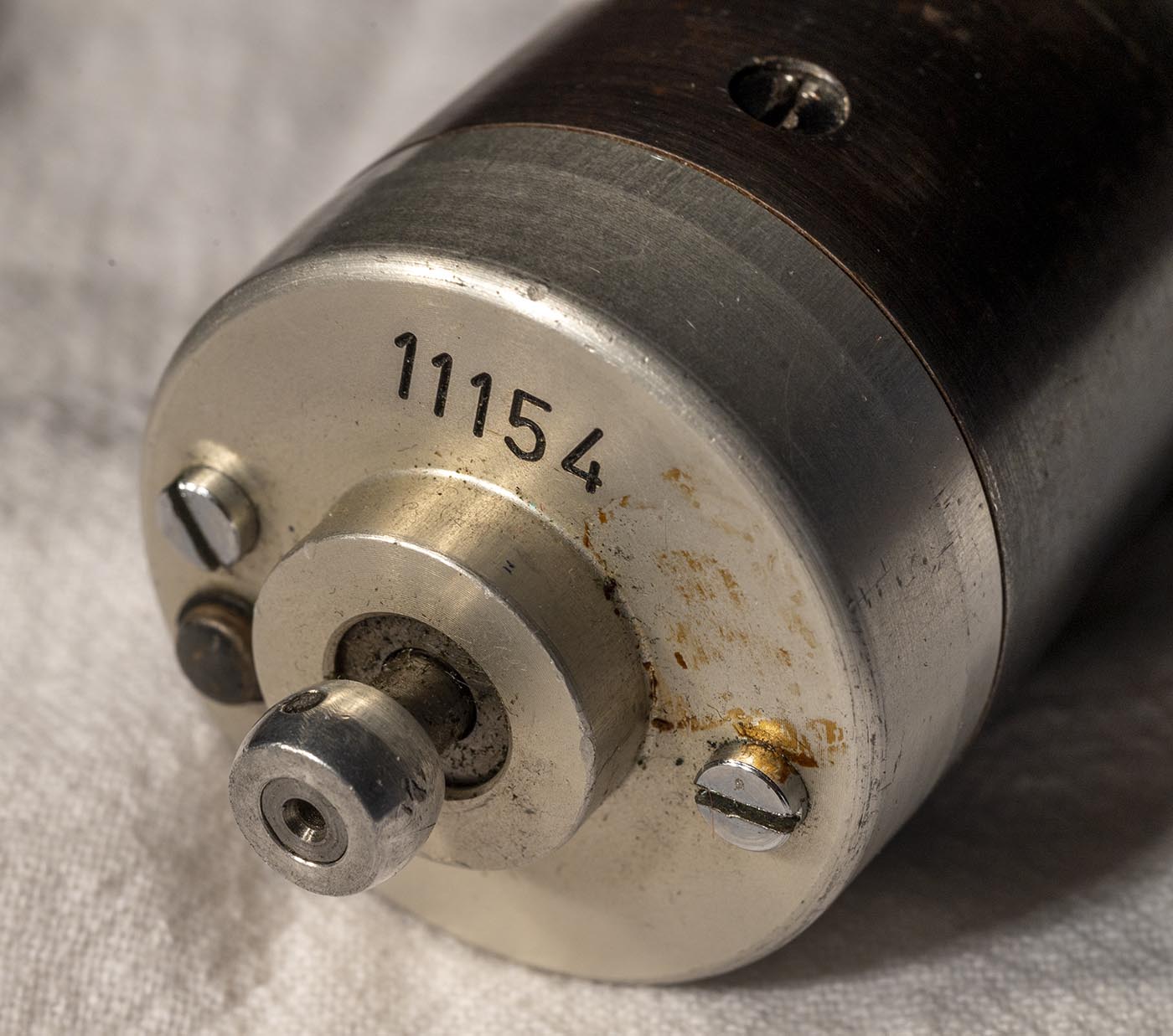
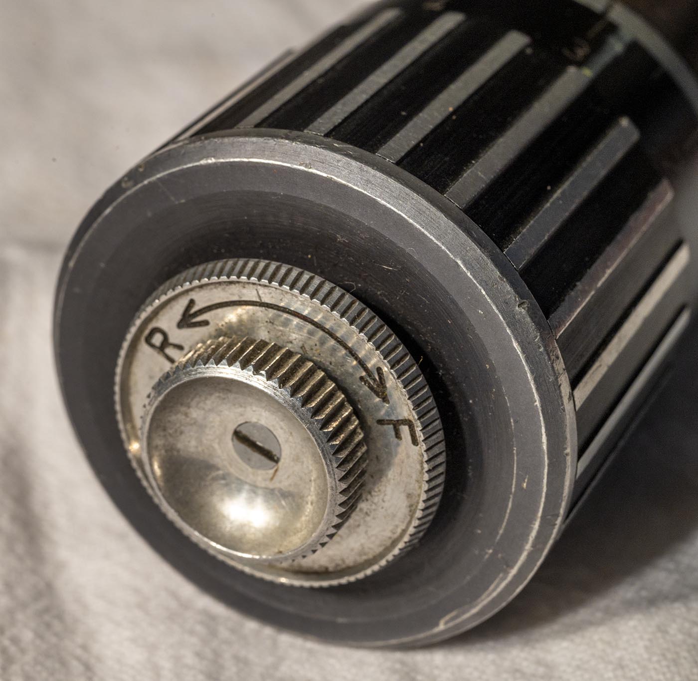
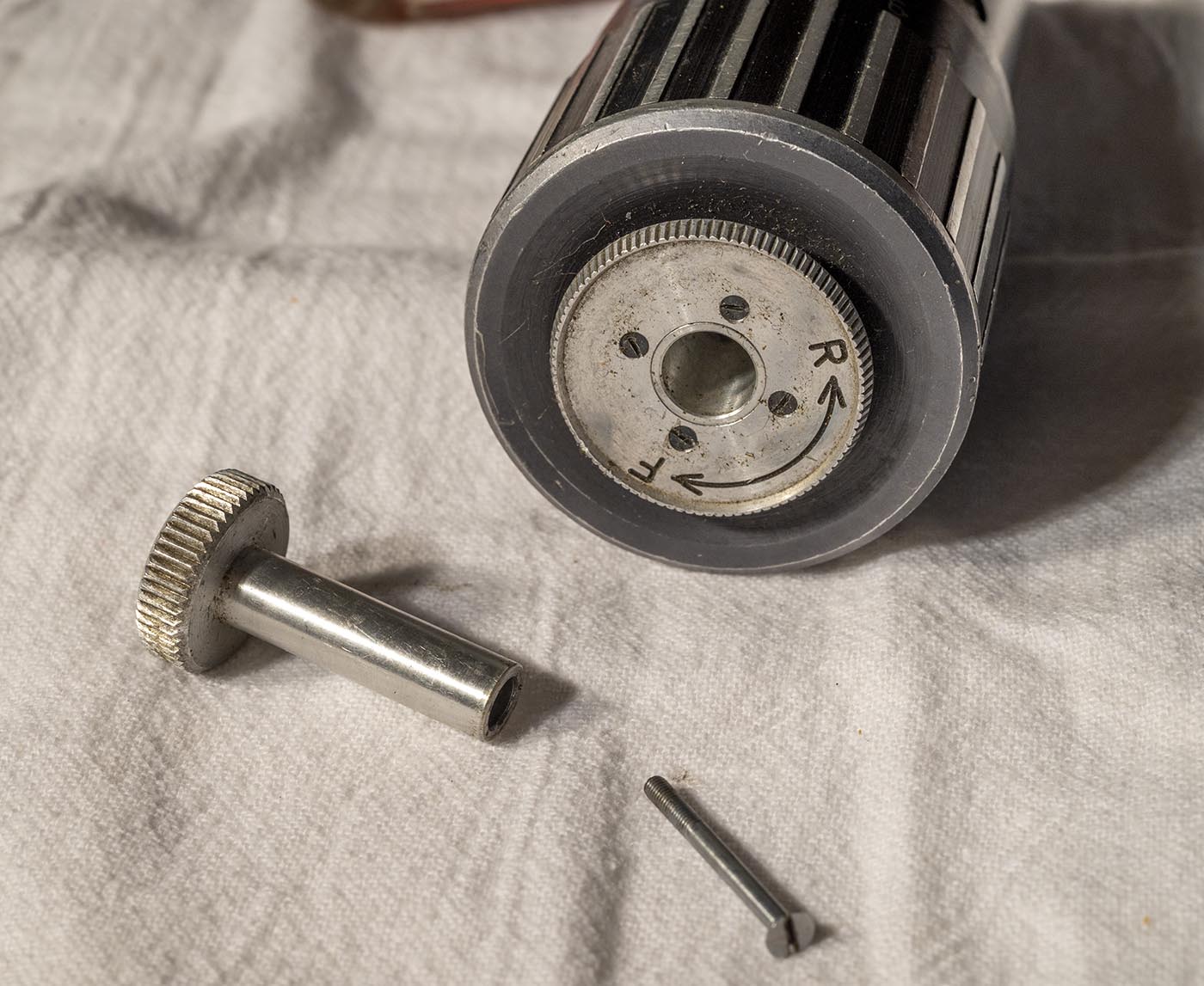
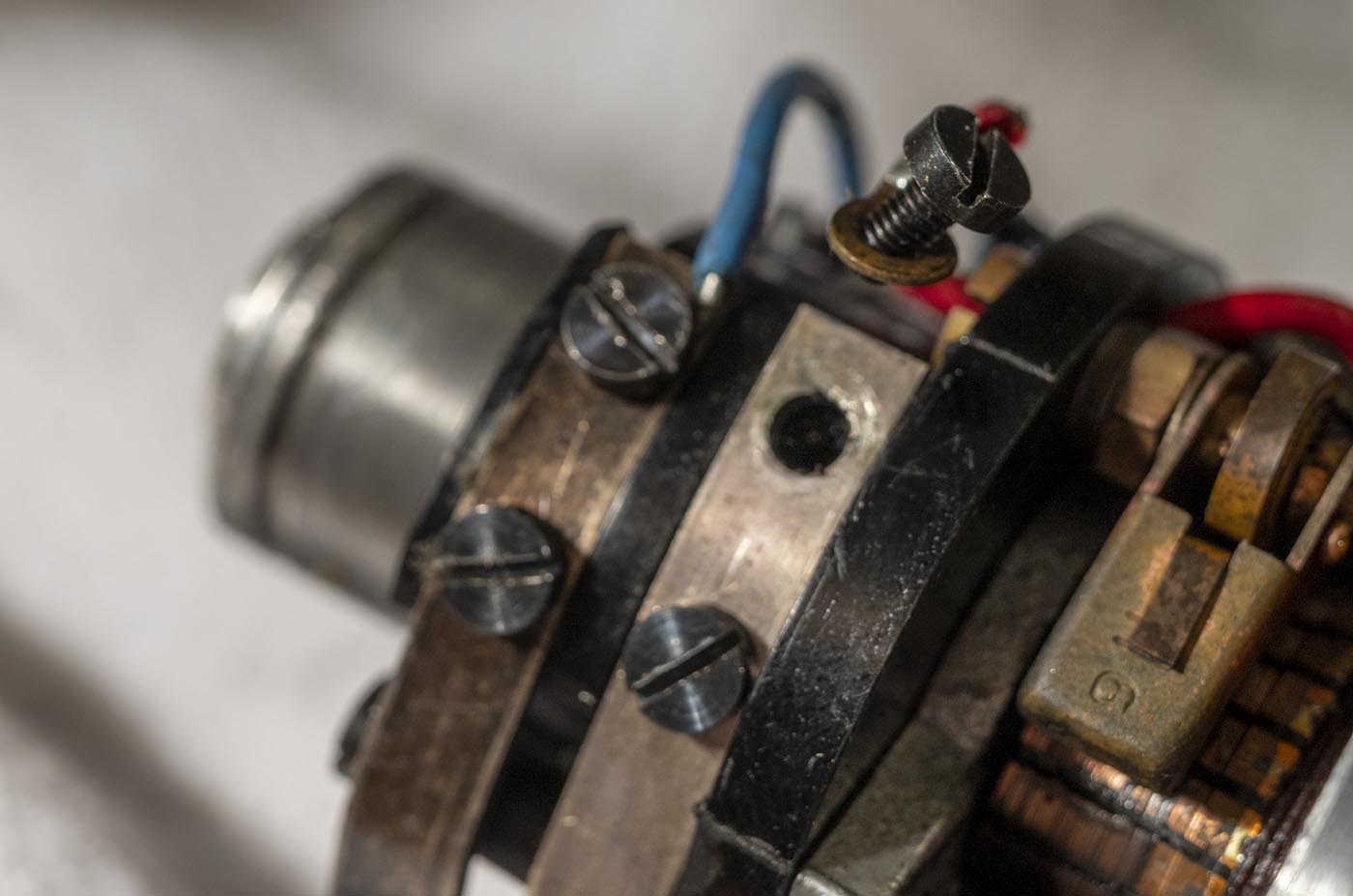
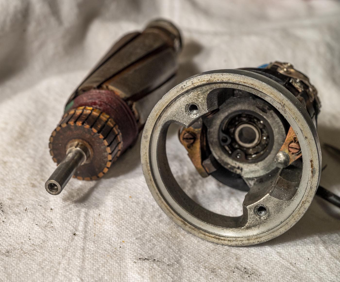
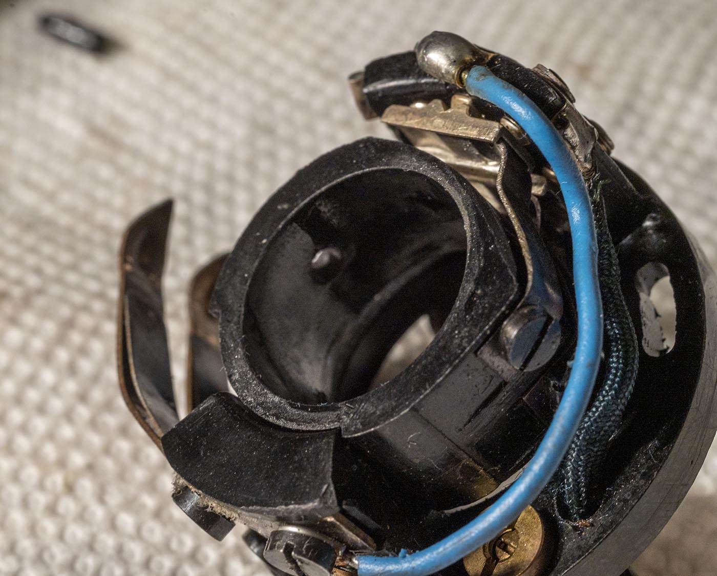
Let's tear down an Arri 16S standard variable speed motor and see what's inside. Here are a few shots of the motor before taking it apart.
(Zooming in on it really shows up all the age related corrosion - it doesn't look this nasty in person!)
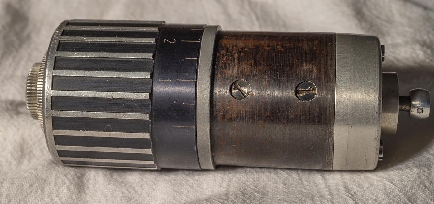
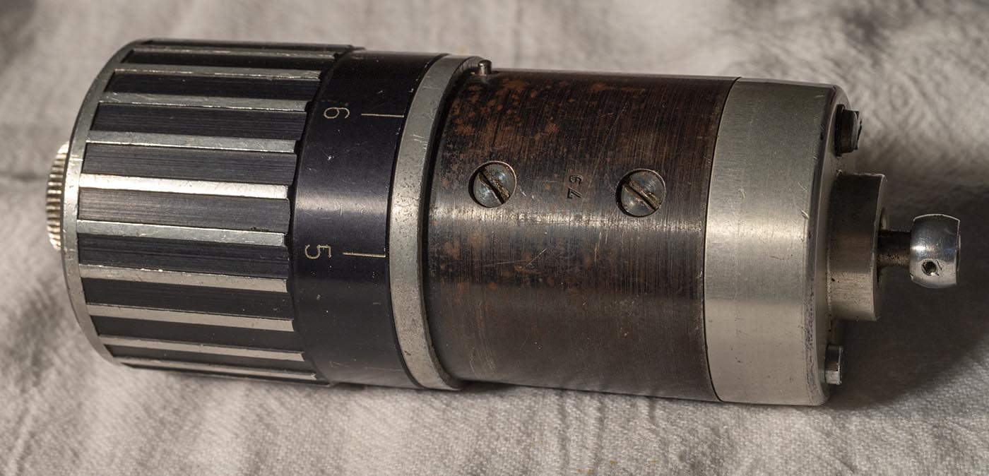
First, we'll take out the obvious screws that hold something together on the drive end...
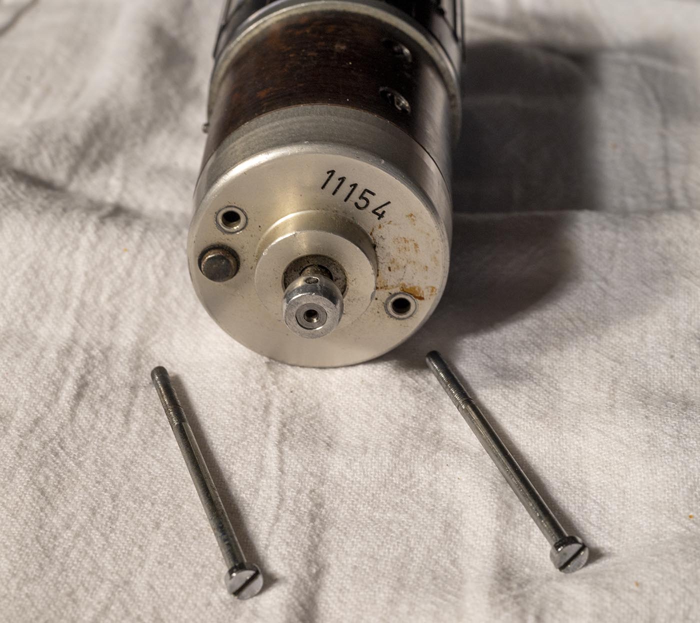
They're really long and go through to the back side of the motor, so we'll leave the front cap alone for now and have a look at the back.
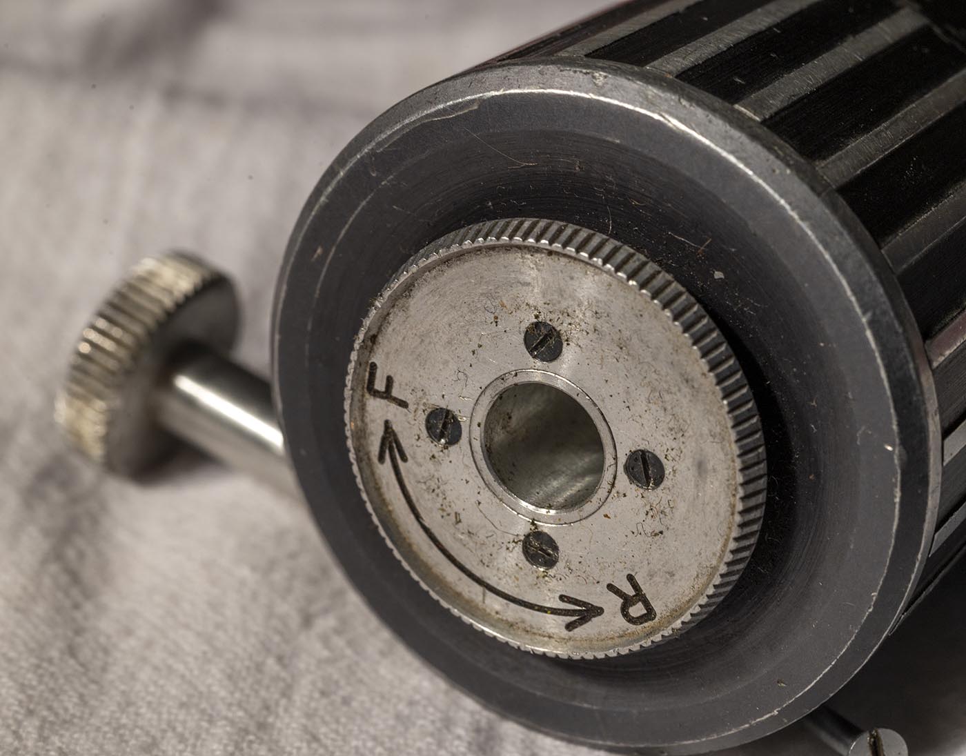
A long center screws holds on the inching knob - that just comes out with a good yank.
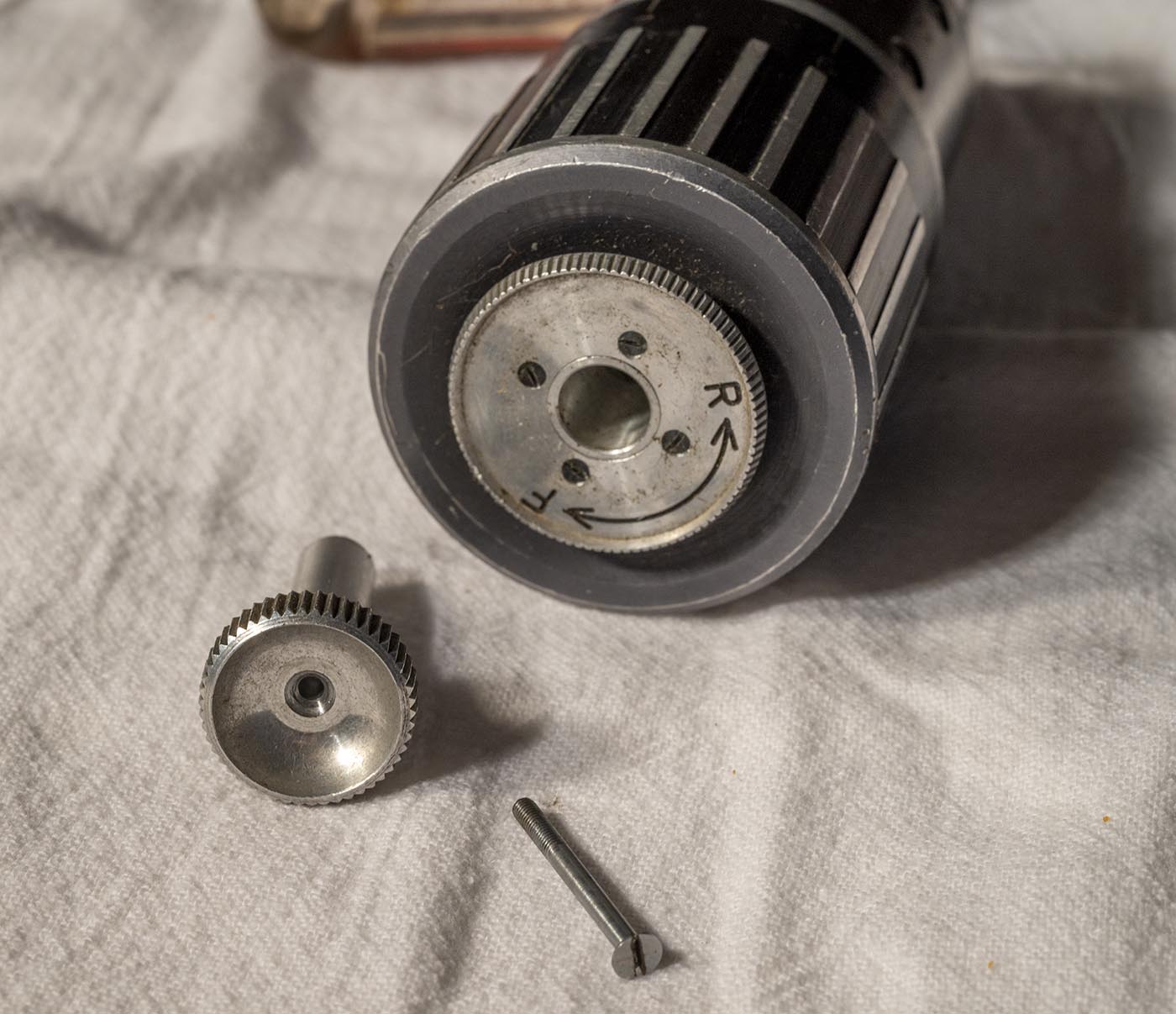
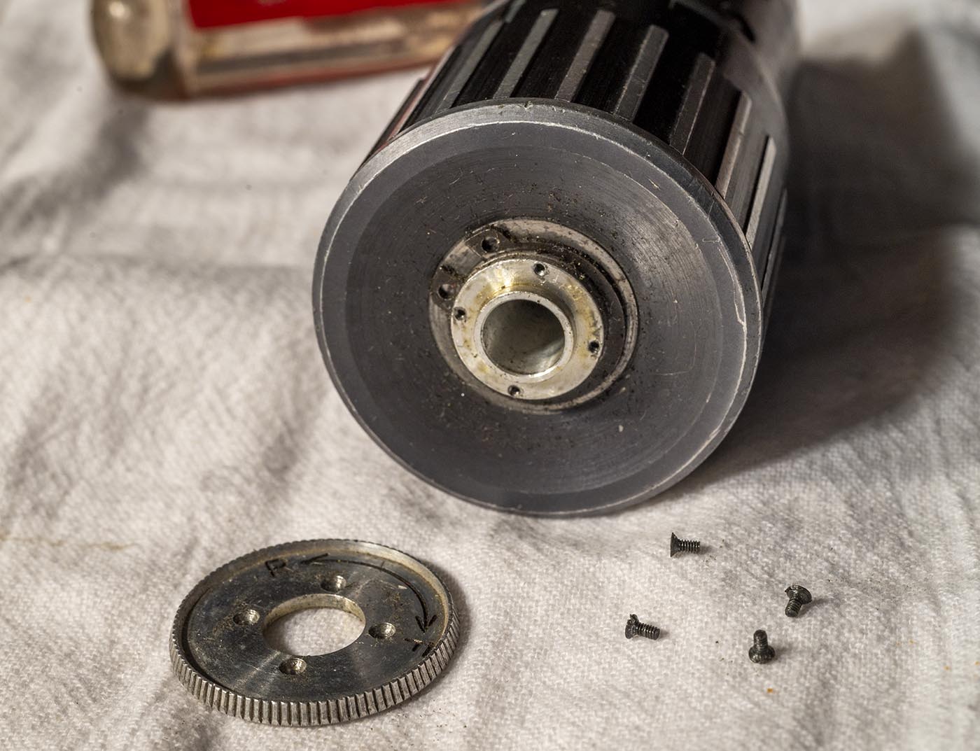
Looks like 4 itty-bitty screws hold on the forward-reverse knob.
Taking those out and the knob off reveals a circlip.
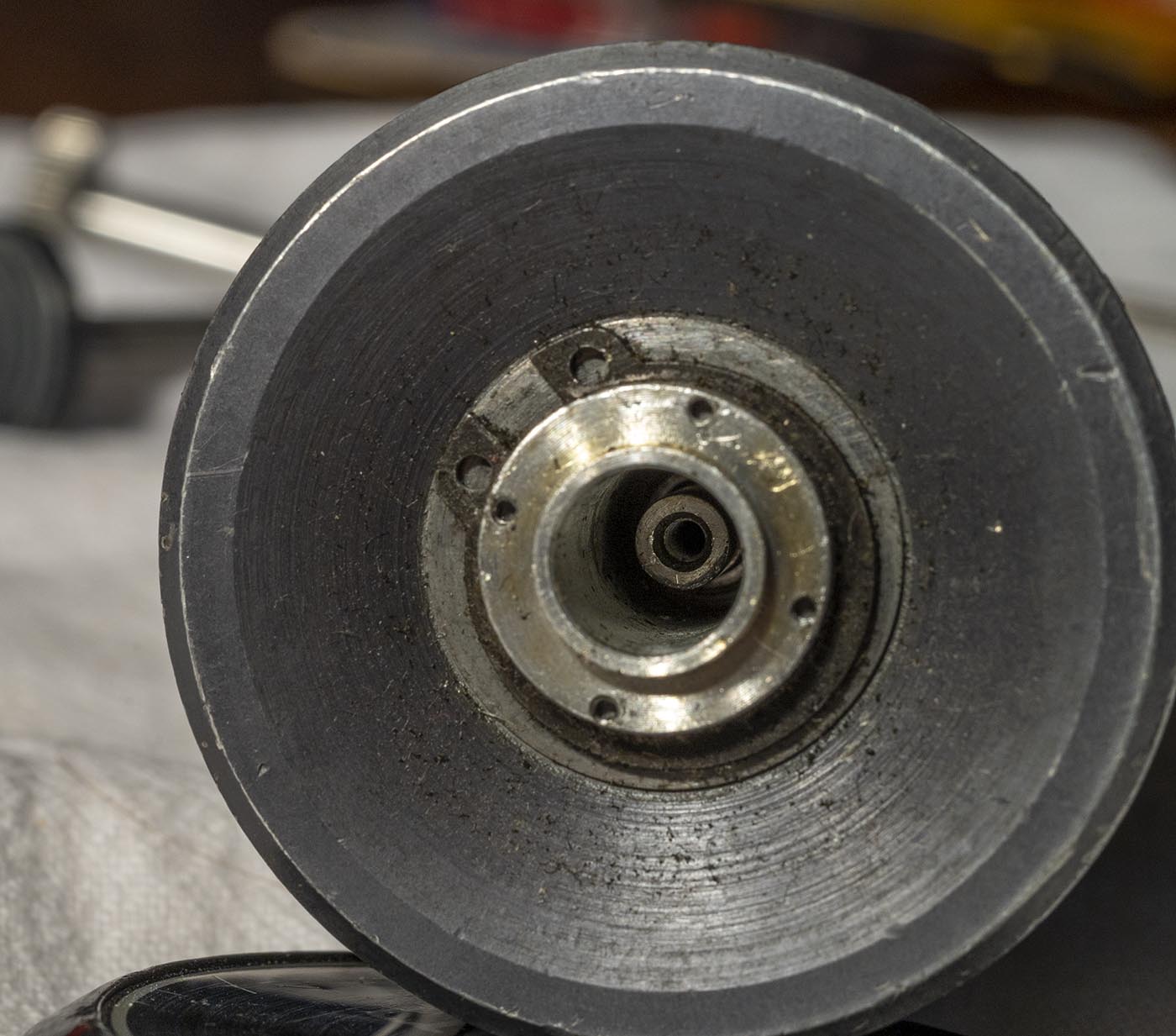
Removing the circlip allows the variable speed housing to come off, with a bit of wiggling.
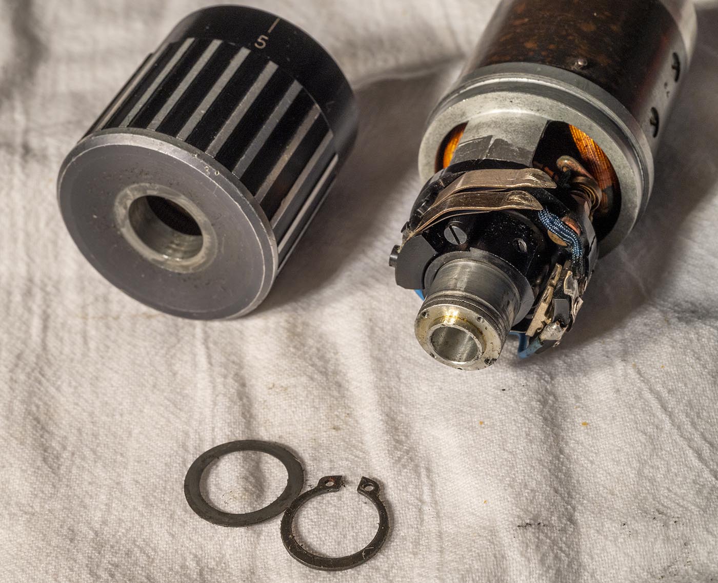
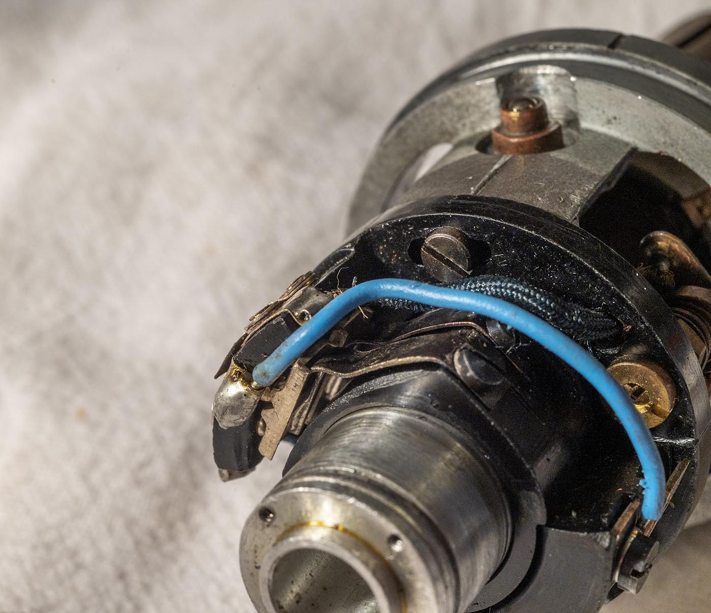
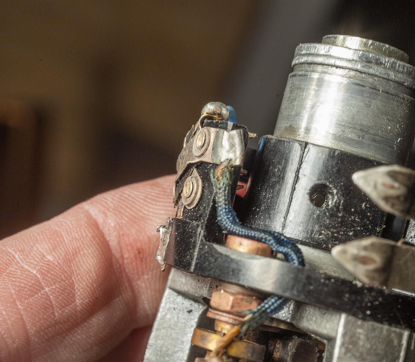
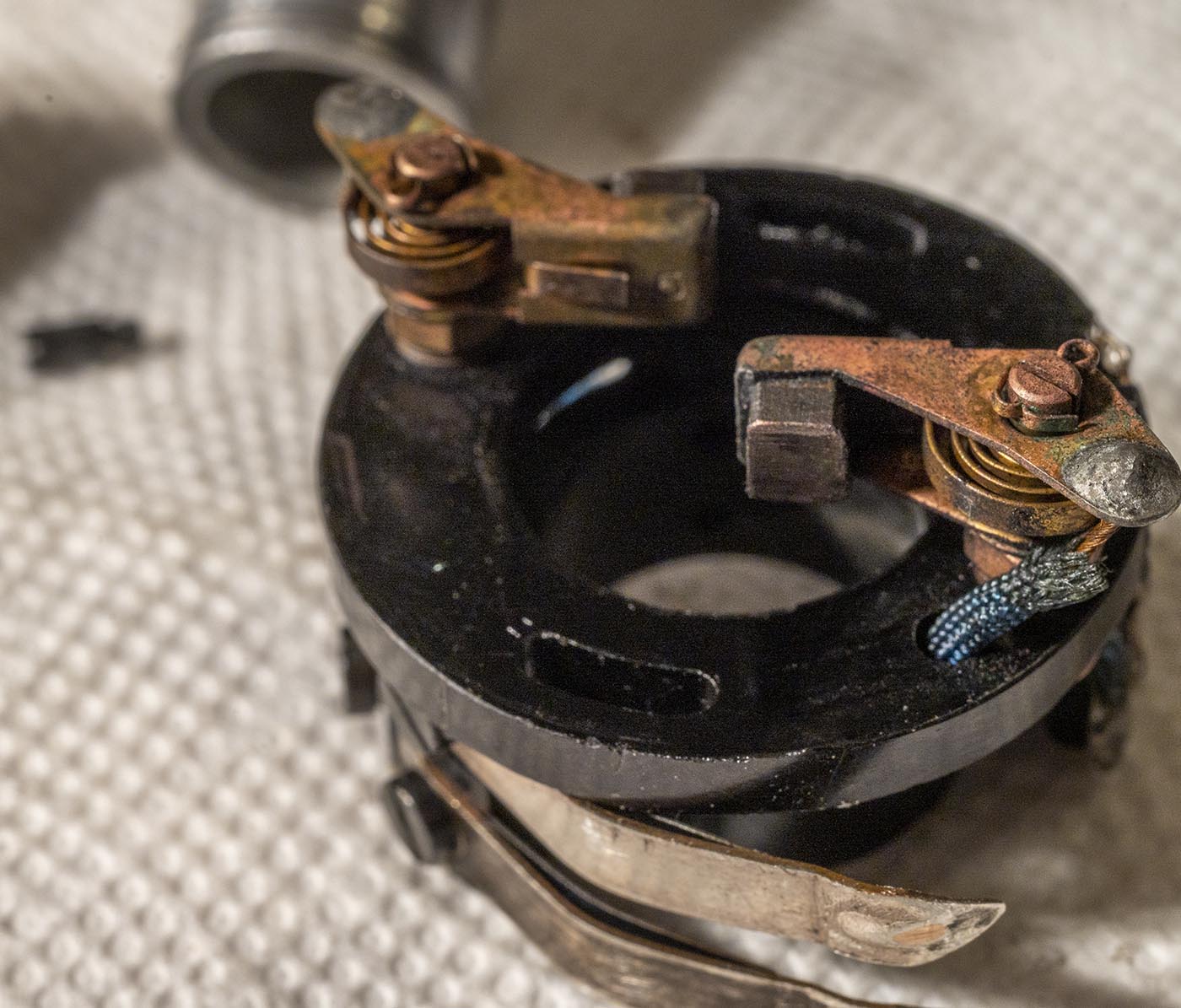
That's what required the wiggling - had to get it past these spring-backed wiper contacts.
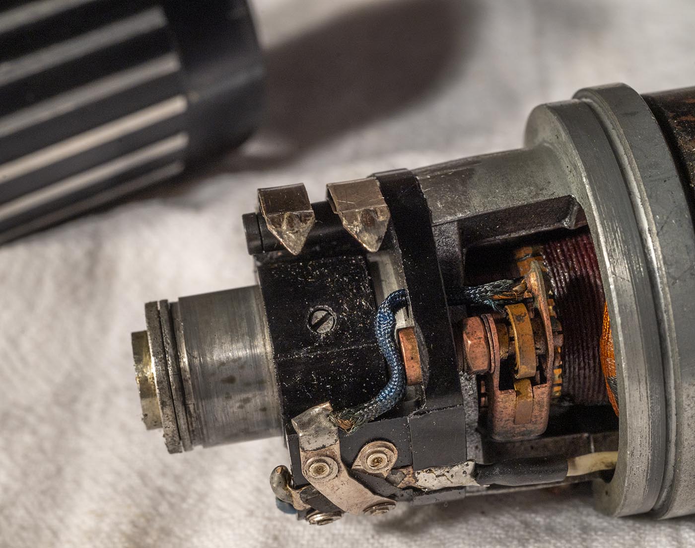
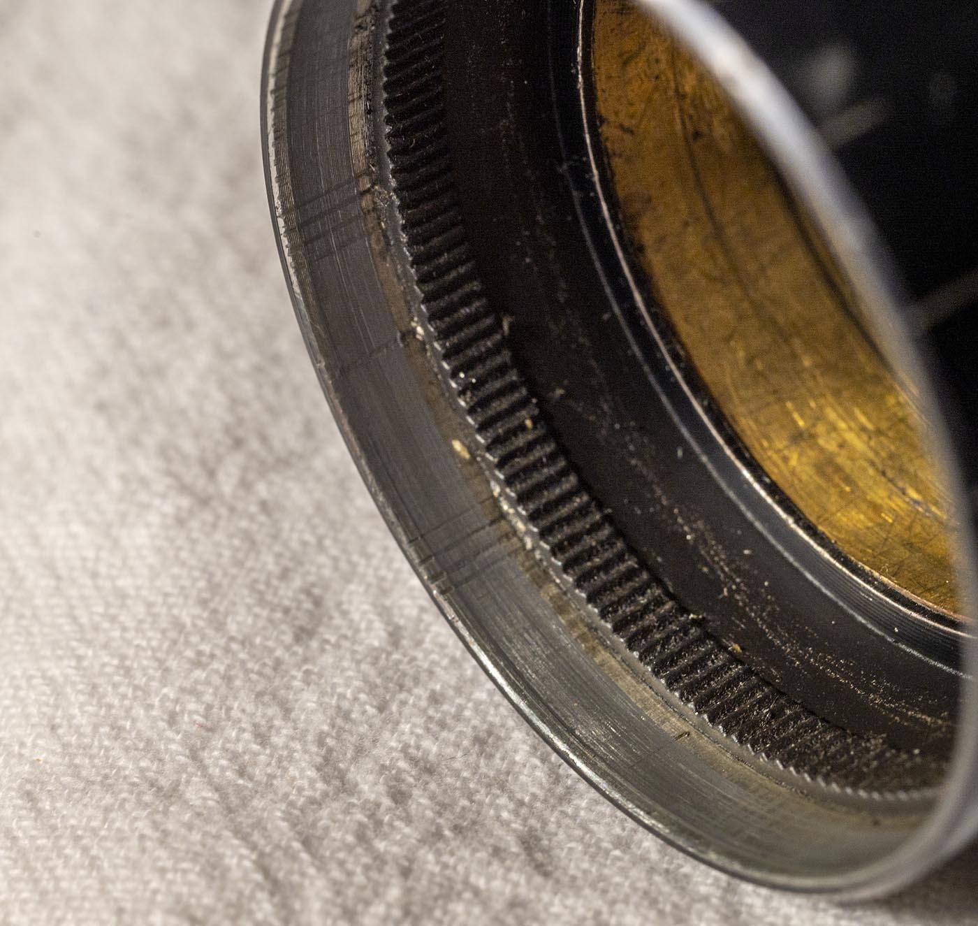
Here is what the wipers wipe against - a variable resistor made up of a length or wire snaked back and forth inside the housing, with apertures that allow
one wiper to hit it...while the other wiper is always rubbing against the copper shell inside the housing. I guess this allows the wear to be distributed
more evenly? By having one wiper wipe on the variable resistor and the other on smooth copper, and they swap about in the middle?
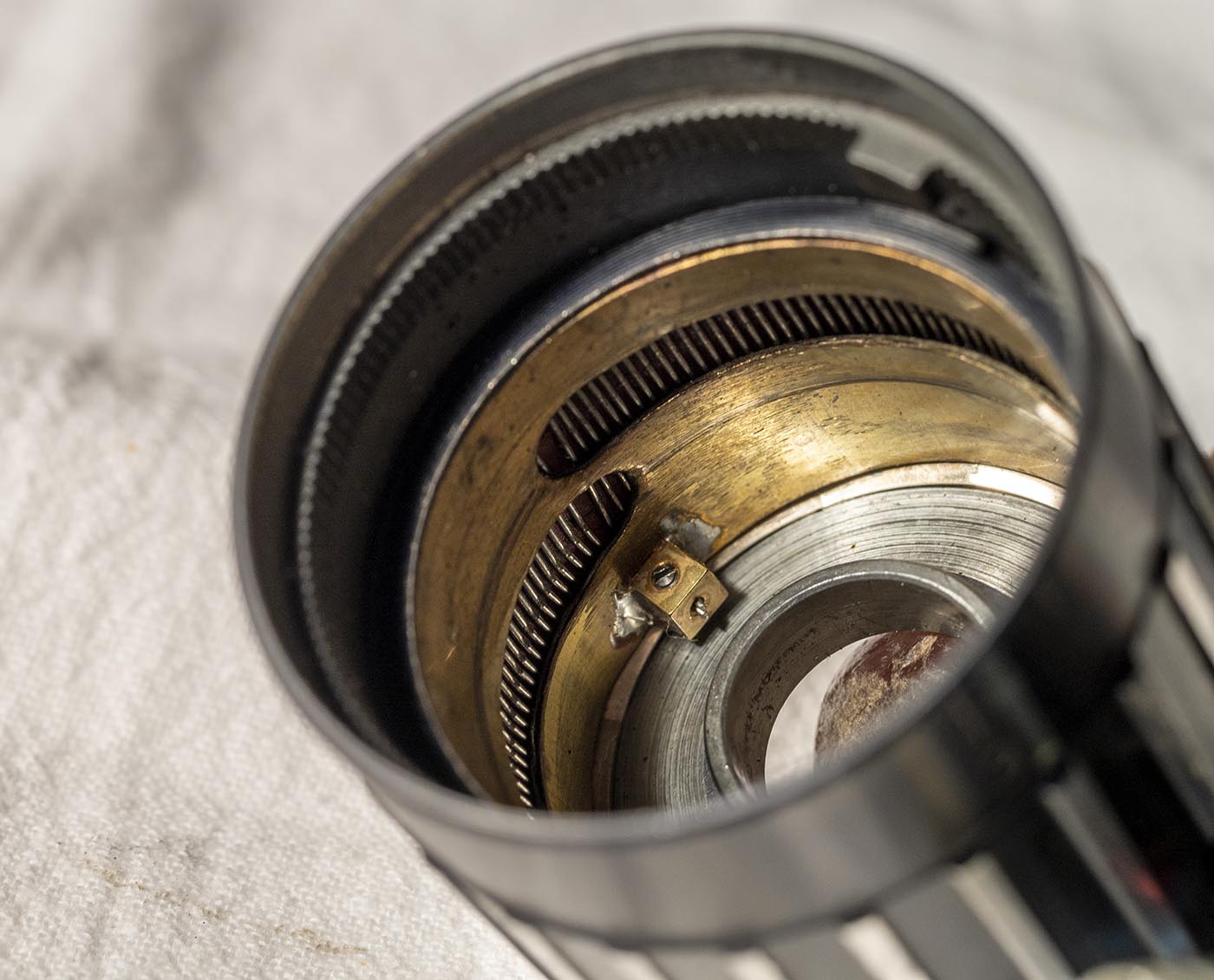
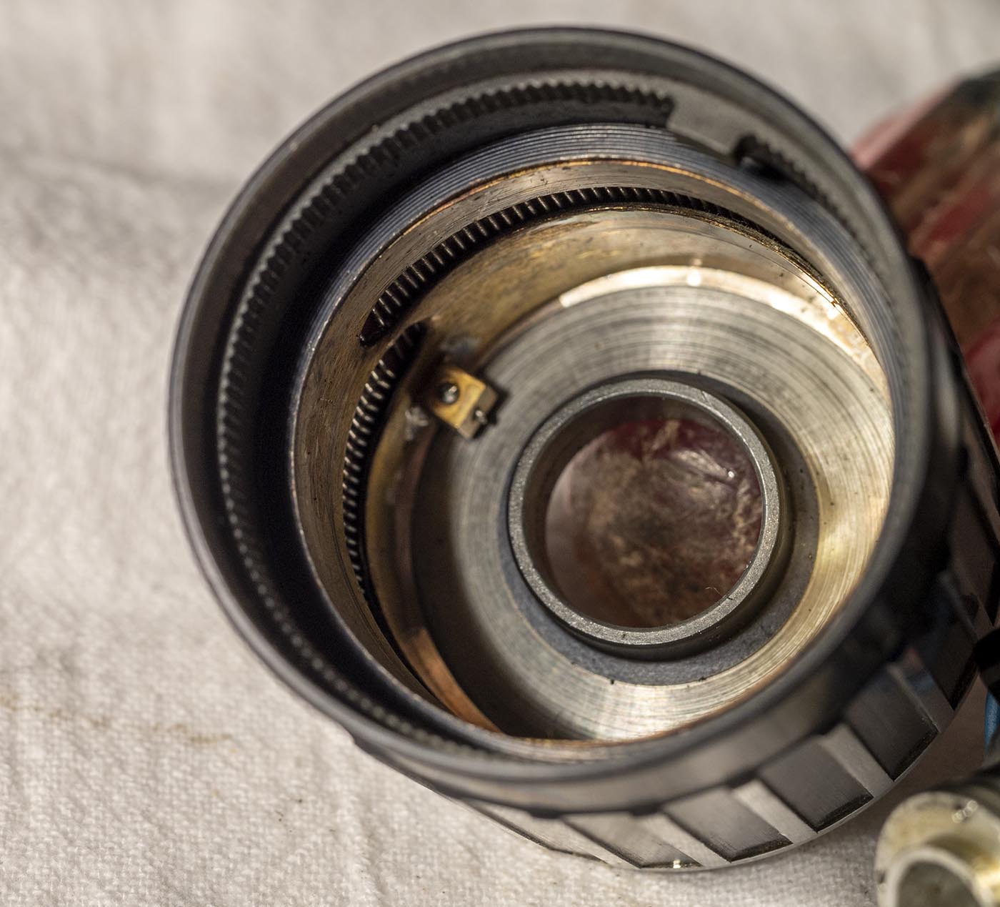
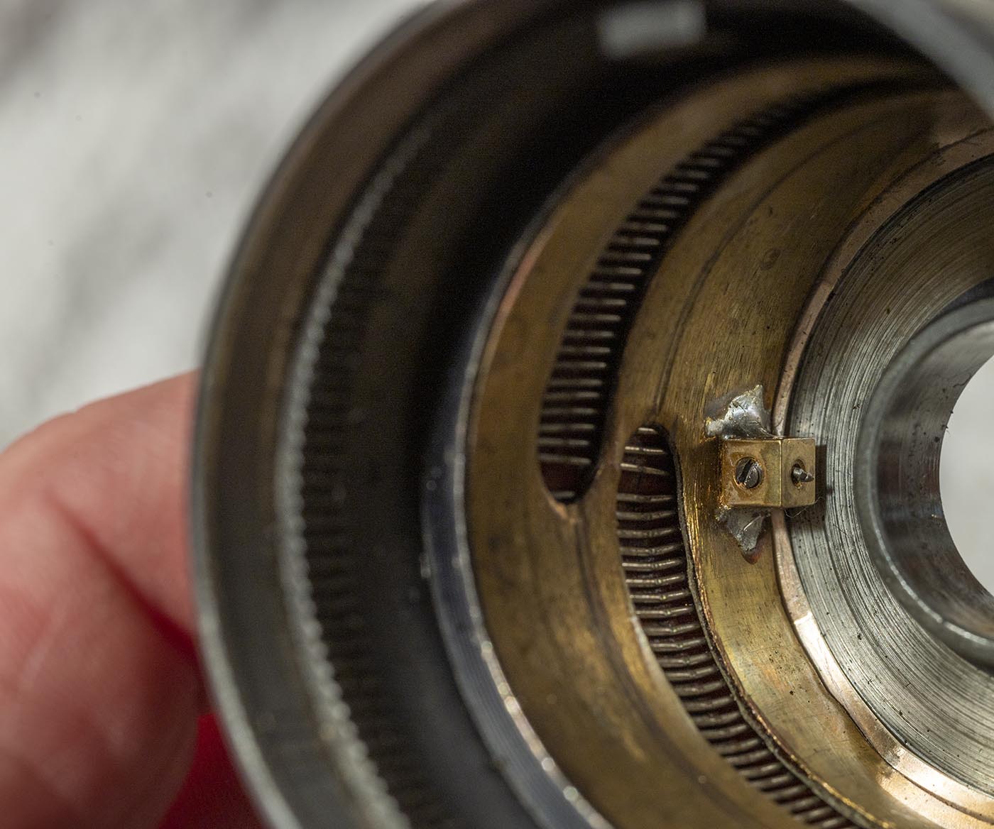
Here is the little spring-loaded ball that provides the "click" feel as you spin the housing.
And here is the toothed track that the ball rides in, making those clicks.
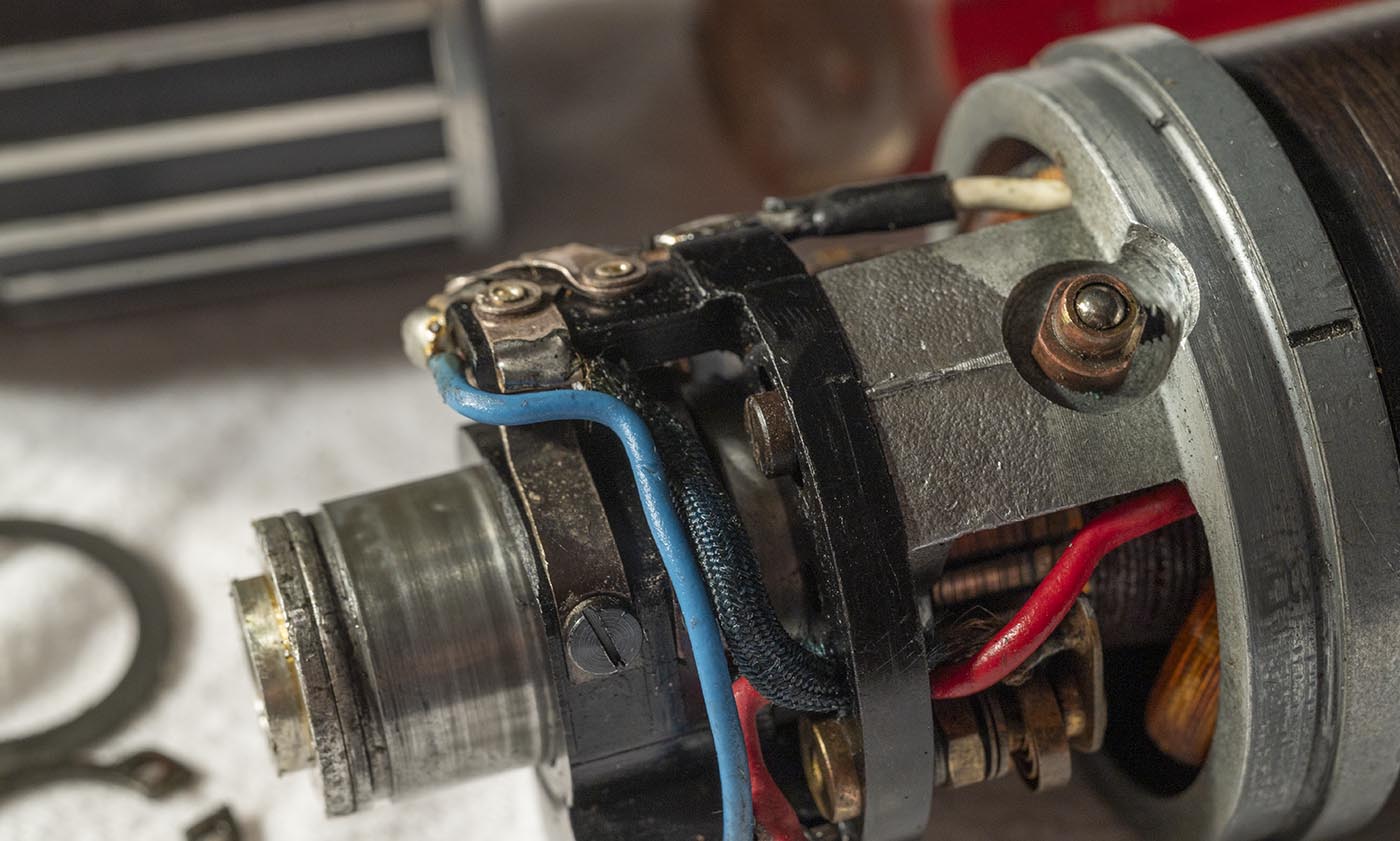
Here is where the two ends of the snaked wire come together and are connected to the copper sleeve. Trust me, you do NOT want to take this part of it apart, ever.
Here is one wire you need to desolder to get it apart. Because this motor can reverse, you need wires from the field magnet coils, rather than having them be
be permanent magnets, like it the constant speed motor. This wire solders to one tab of the reversing switch (criss-cross!)
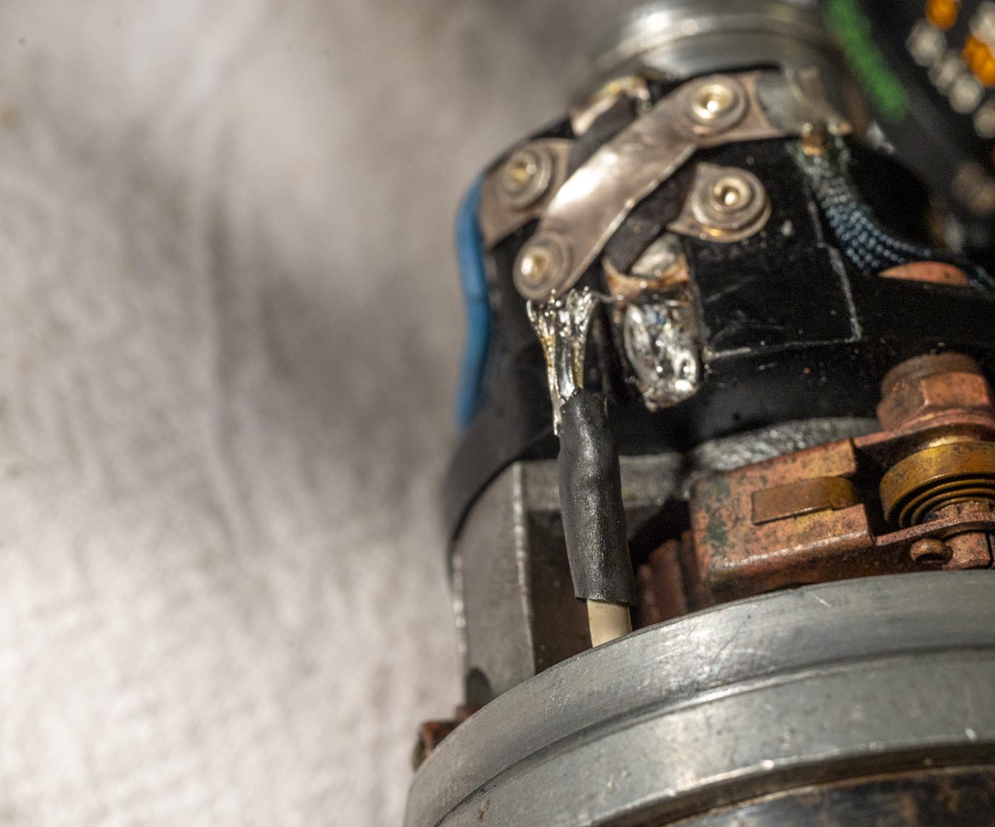
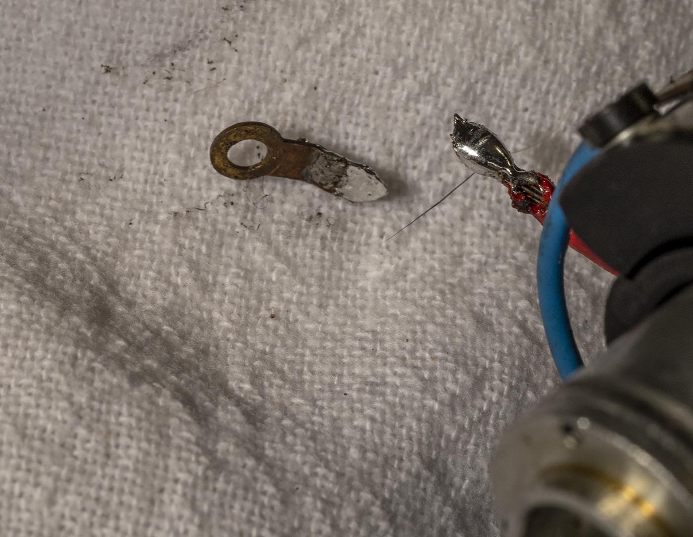
Here I removed the screw holding the ring terminal on the contact, so I could desolder it away from the structure and not risk melting the plastic mounting plate.
DO NOT DO THIS! IT WAS A MISTAKE! The "plastic" is Bakelite, which can handle the heat. What it can't handle is having the screws run in and out of
it mutiple times, as it was bad engineering to have threaded holes in bakelite and expect screws to hold in them. Just desolder the wire from the ring terminal, in place.
Now the armature and rear mounting structure can all just pull out of the main housing. Careful when threading those two wires through things as you separate the parts.
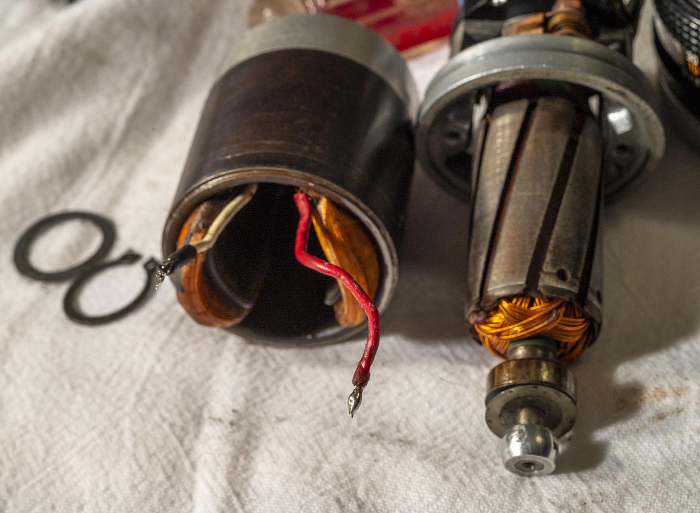
The red wire is soldered between the field coils, and there's a cap or something in there. The white wire goes down into the depths.
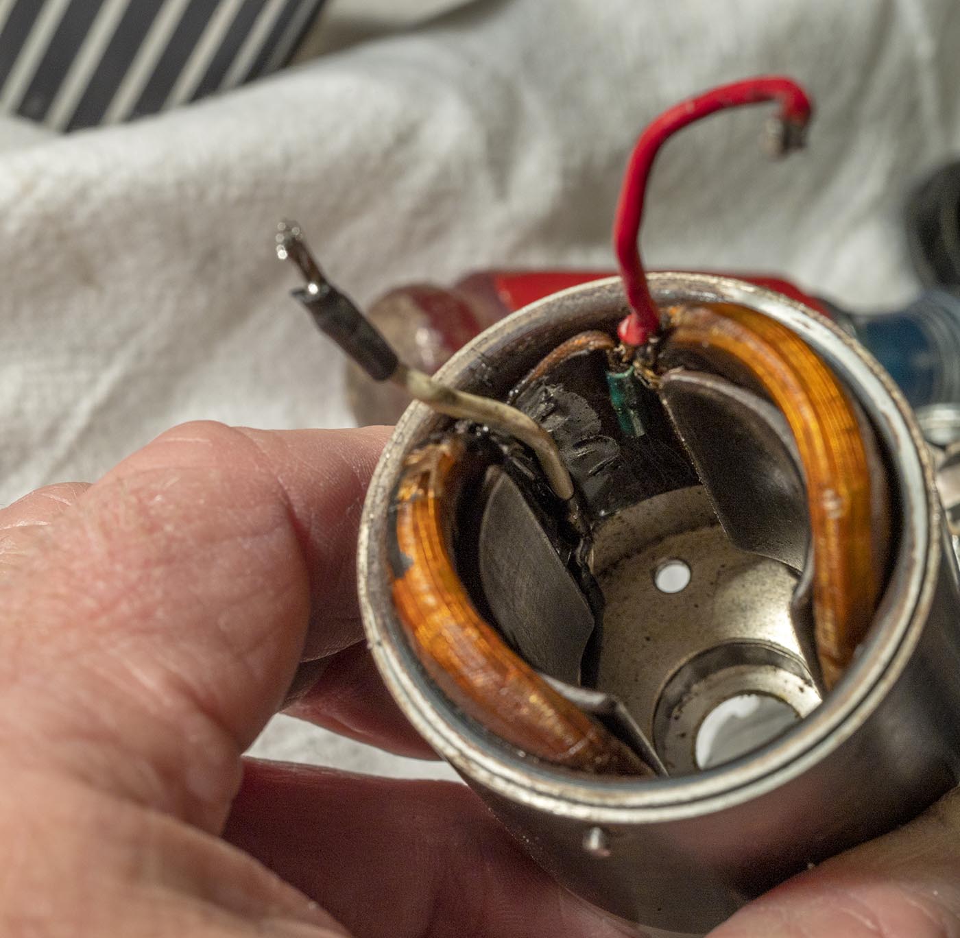
Ah, the white wire connects to the motor power contact on the front plate.
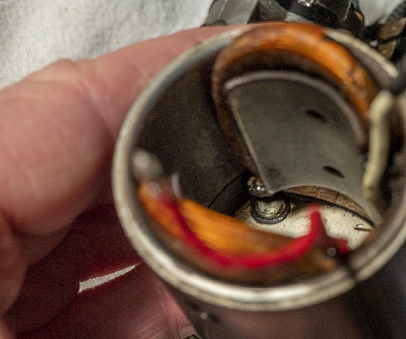
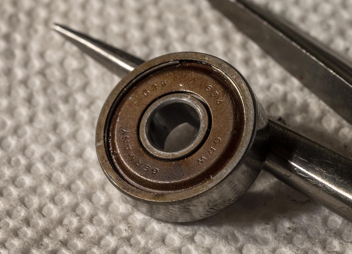
The same old GRW 625 bearing we've seen in the other motors, but this one is open on one side for one reason. This particular one is filled with nasty grease.
Someone has been in here before, greasing the bearings instead of replacing them.
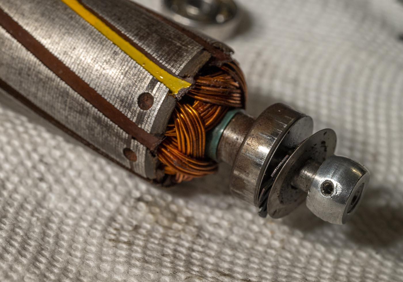
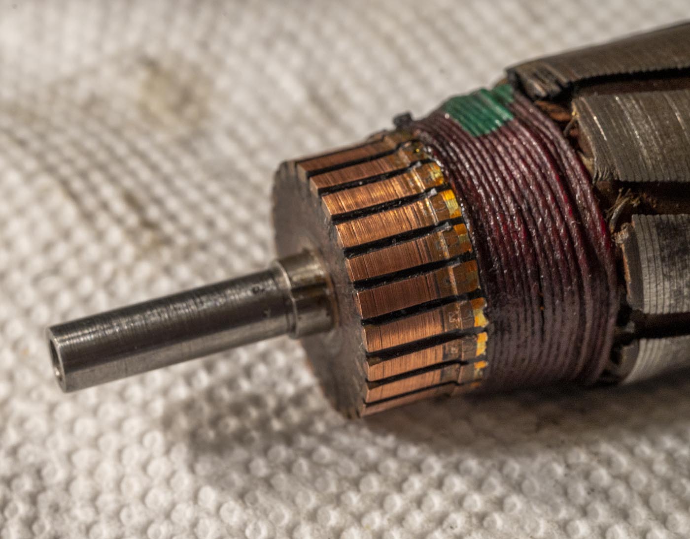
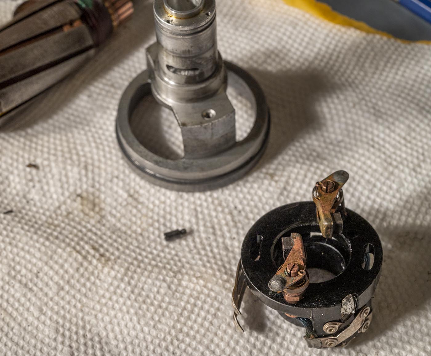
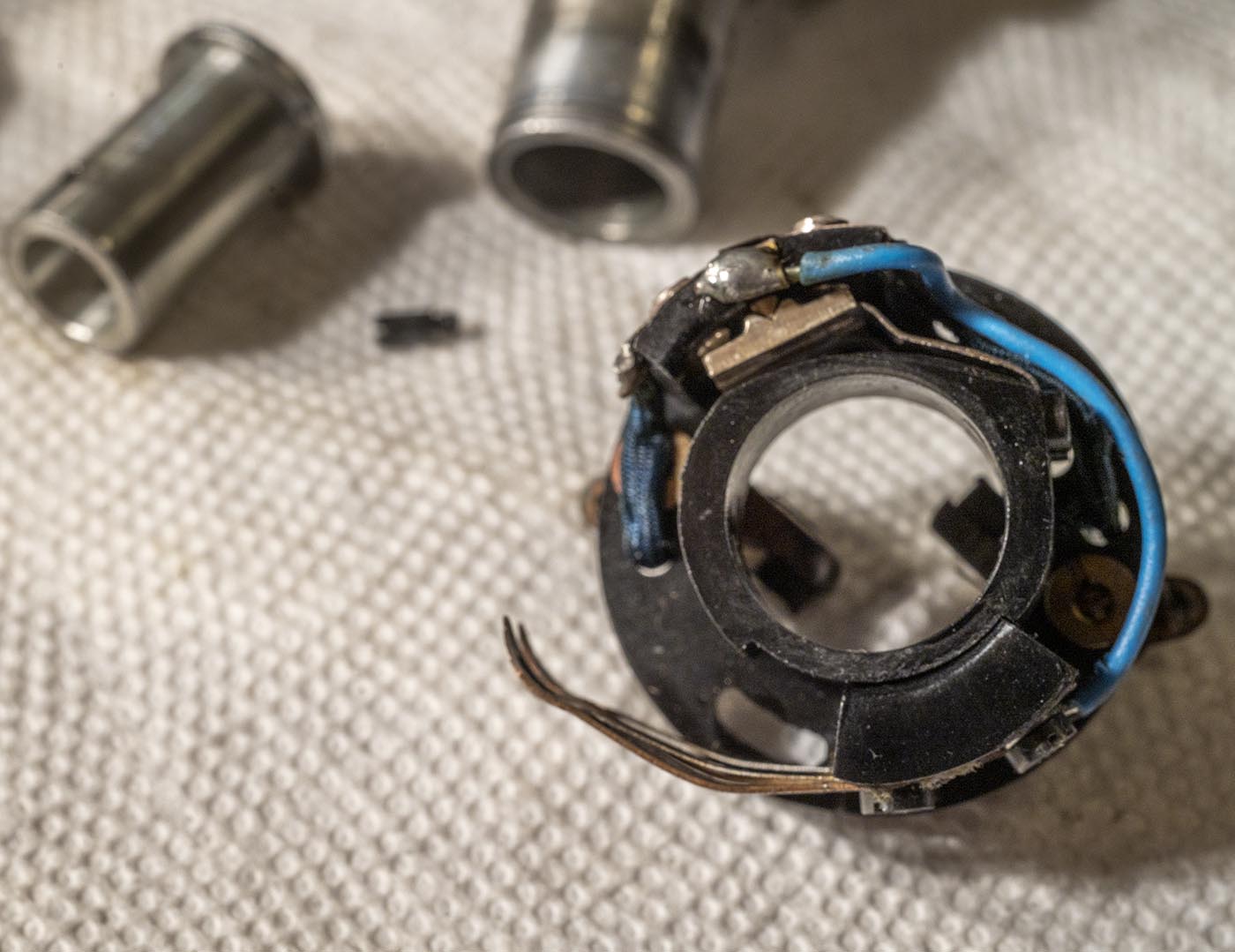
Here is what we have now, the armature and the rear brush/direction switch assembly. For some reason, one of the insulators on the armature is painted yellow.
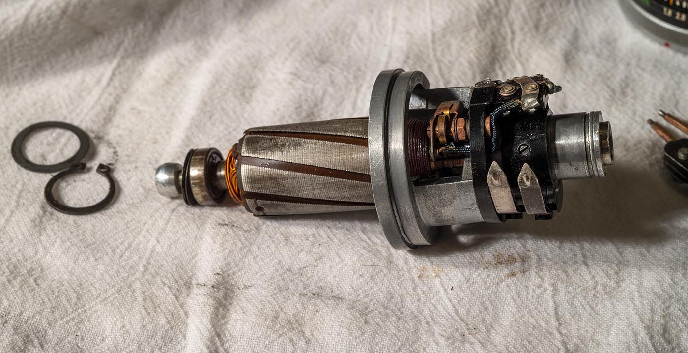
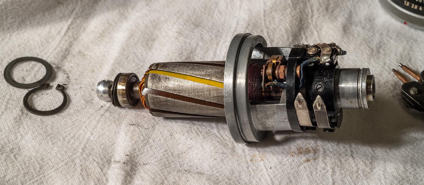
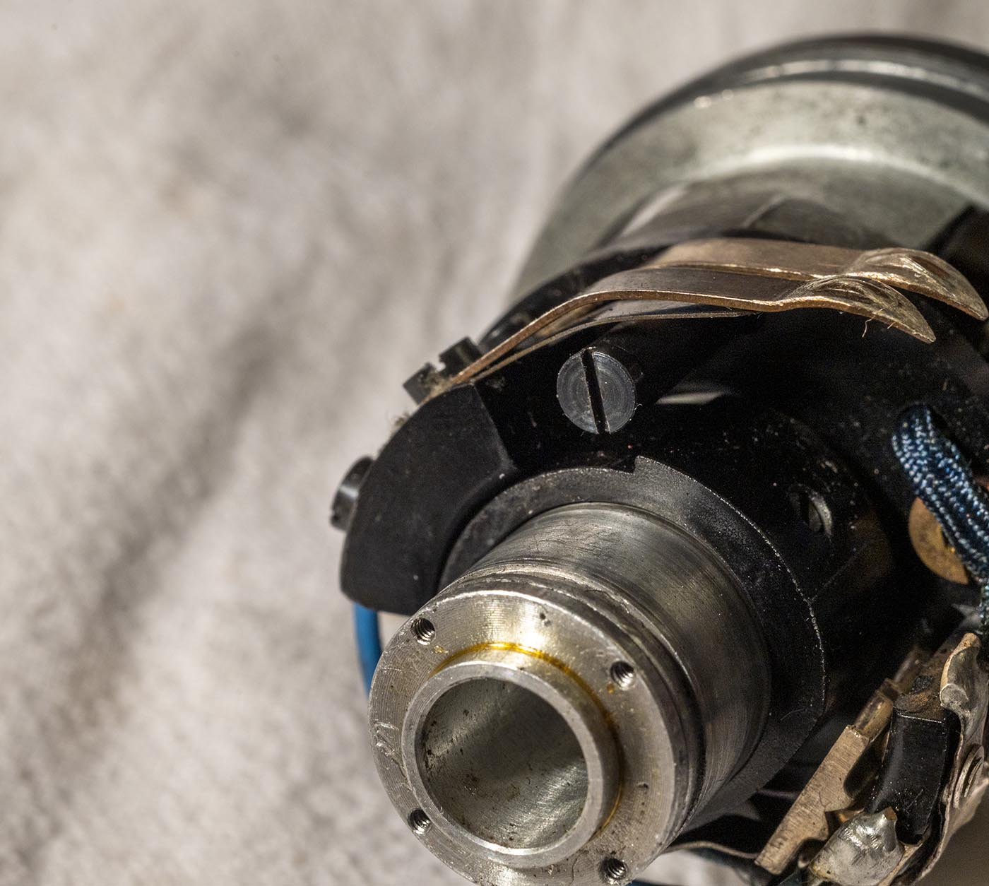
These two screws hold the switch assembly onto the bearing holder. One of them goes through a rubber tube that acts as a support for the wiper contacts.
The holes are slotted. Make a note of where the screws are positioned (on mine, the indents from the screws marked it precisely.)
With a firm yank, we can get the armature out of the rear bearing and have the whole rear assembly separated.
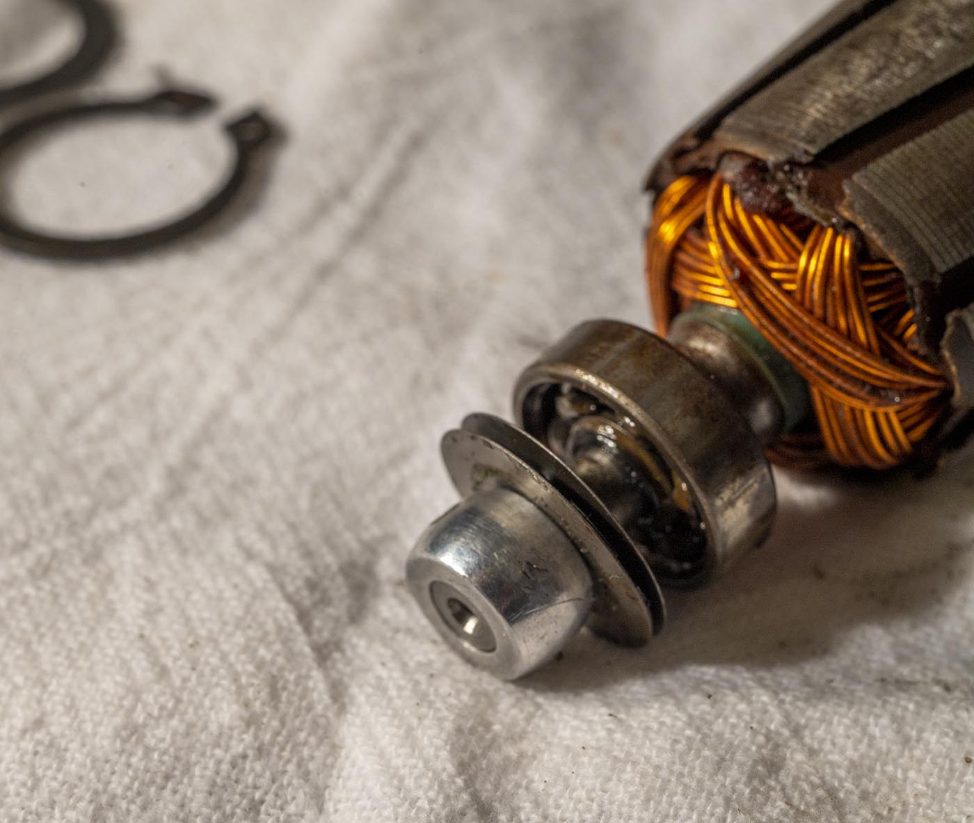
Motor brushes are actually in pretty good shape! Another bearing that's been refilled with nasty grease.
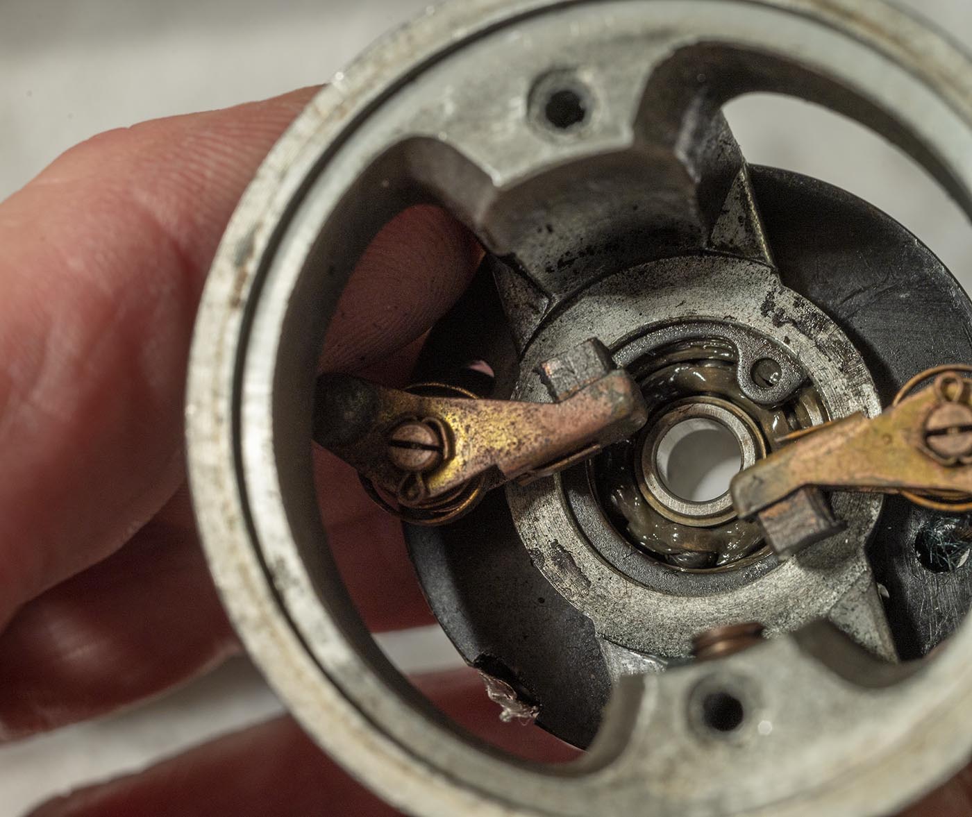
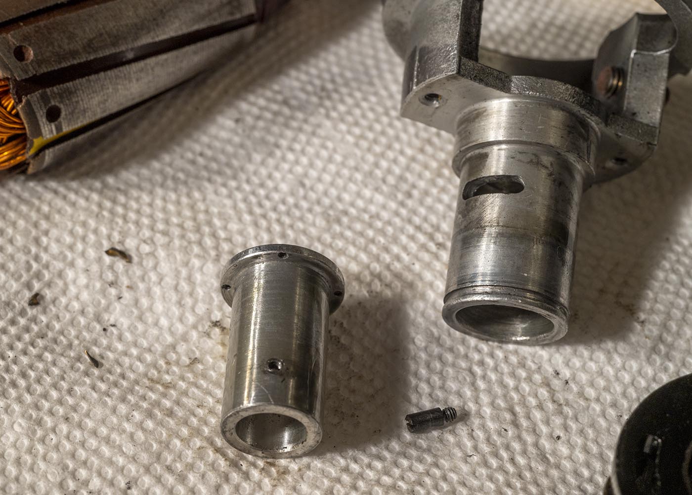
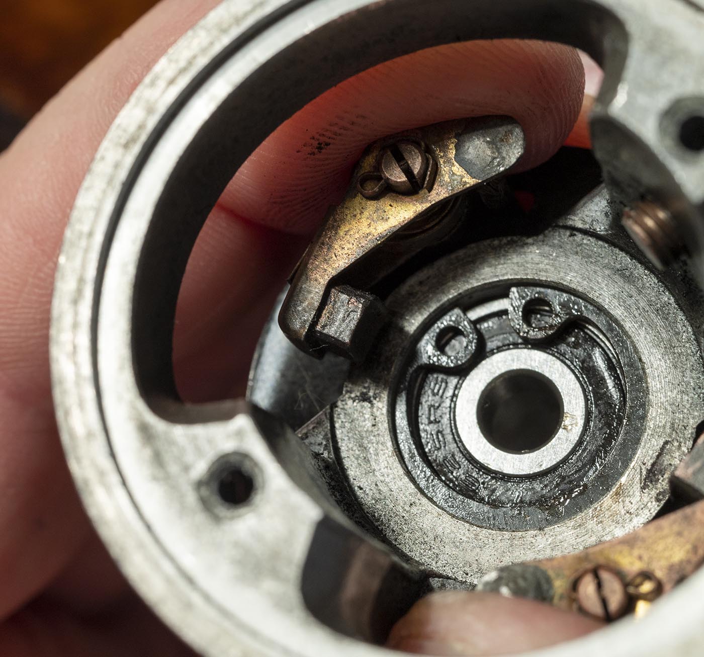
A circlip keeps the rear bearing in the holder, remove it to remove the bearing.
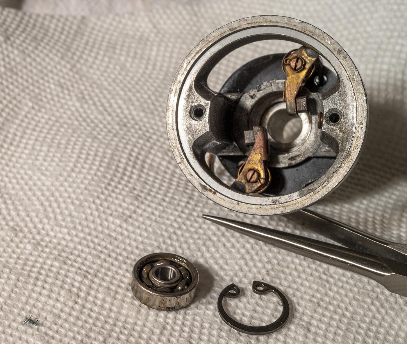
Same old GRW 625 bearing (with the same old extraneous "634" marking. Let's take some measurements to see if it matches the generic "type 625" bearing sold everywhere.
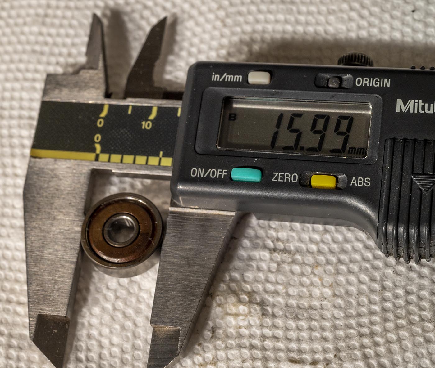
16mm outer diameter. Check.
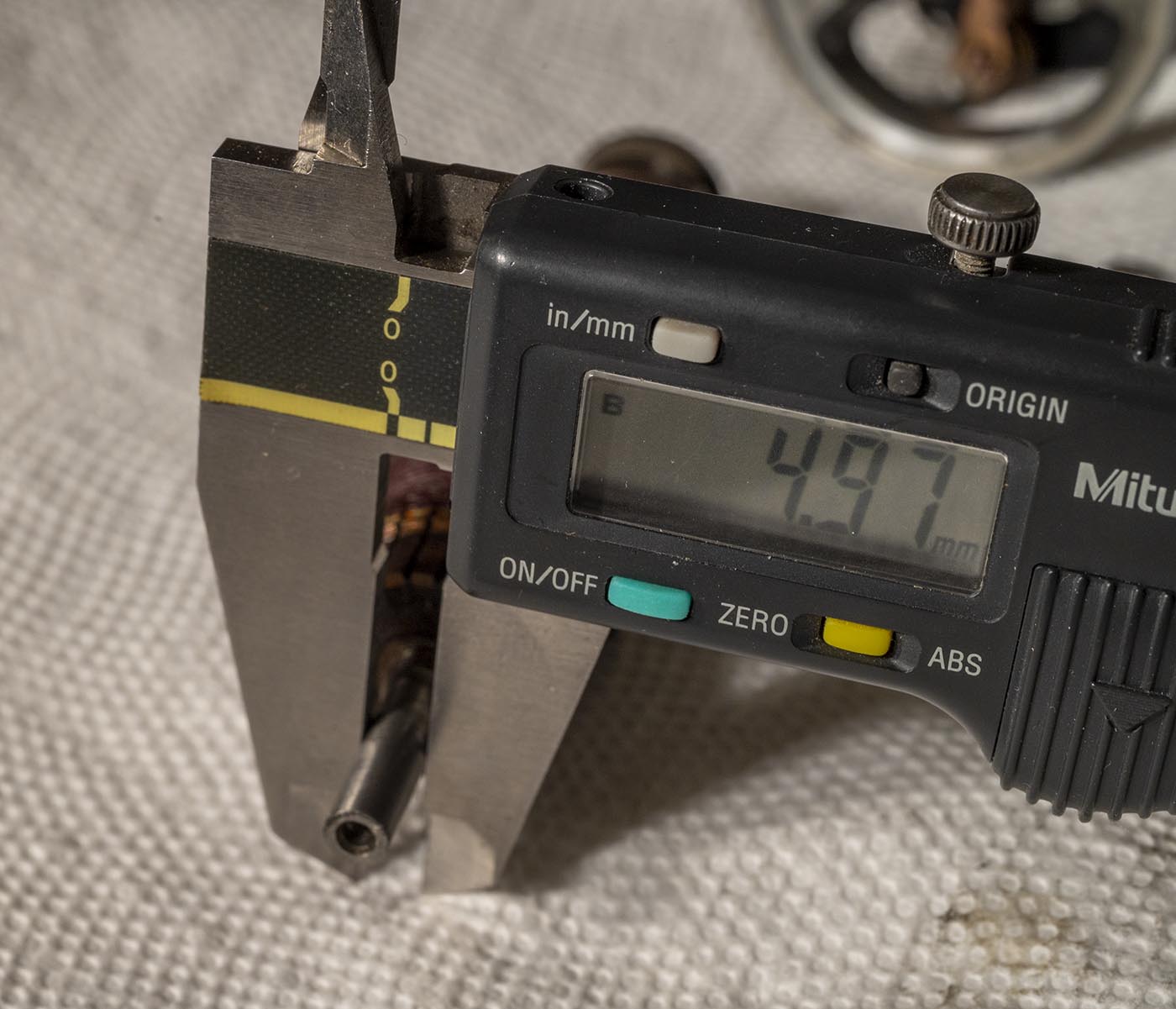
5mm shaft diameter. Check.
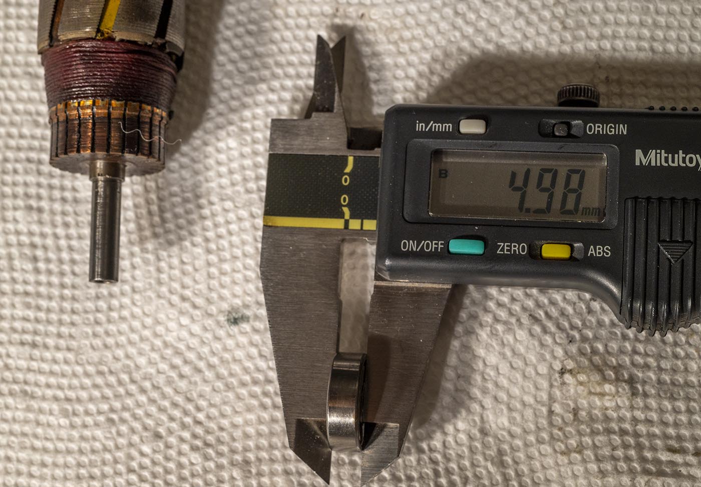
5mm race depth. Check. Yep, that's a type 625 bearing!
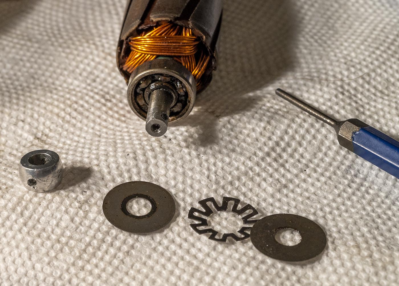
This motor has a springy washer in between two thin flat washers/dust shields, all pinned against the case in front of the bearing when assembled.
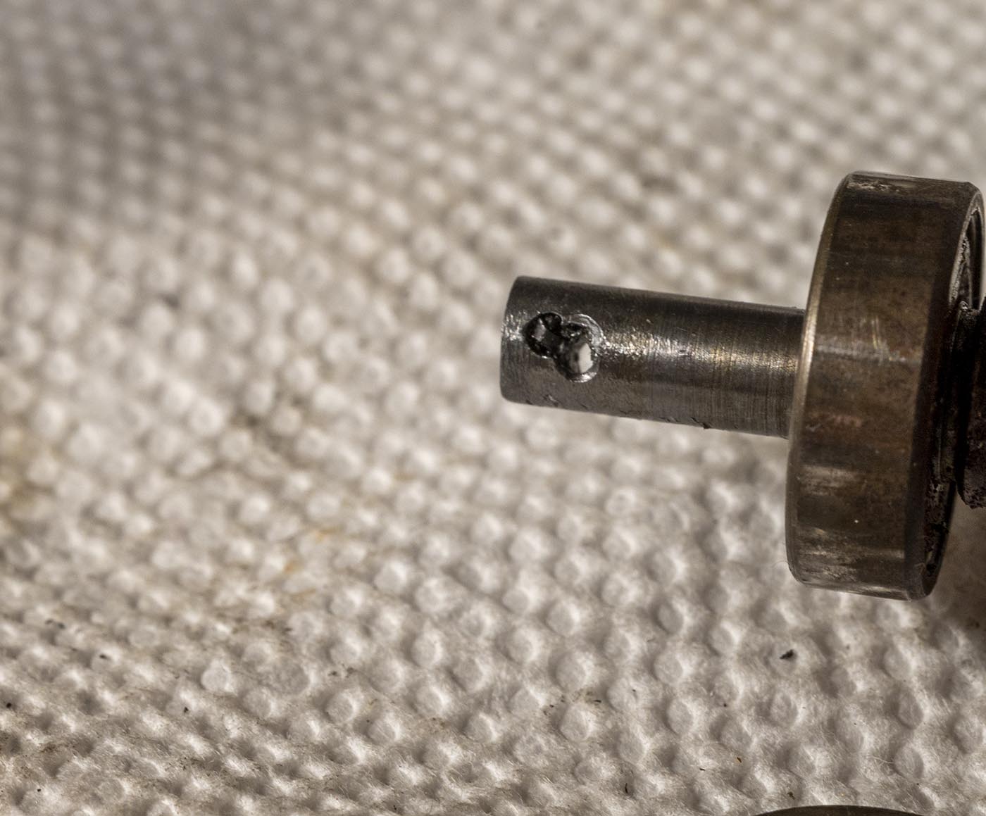
I still haven't quite figured out what they use as a cross-pin to hold the ball drive on. It's steel, it's not a roll pin, no force I can bring to bear on it
will budge it from either side. In both cases I've done now, I've had to drill in from both sides to get the ball off, then punch out any remaining bits.
It's hard to keep the drill going straight, even in a drill press...
Armature contacts clean up nicely with insanely-fine-grit sandpaper.
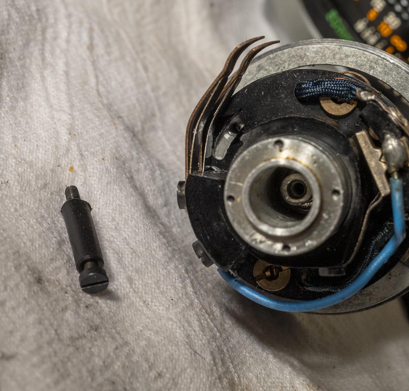
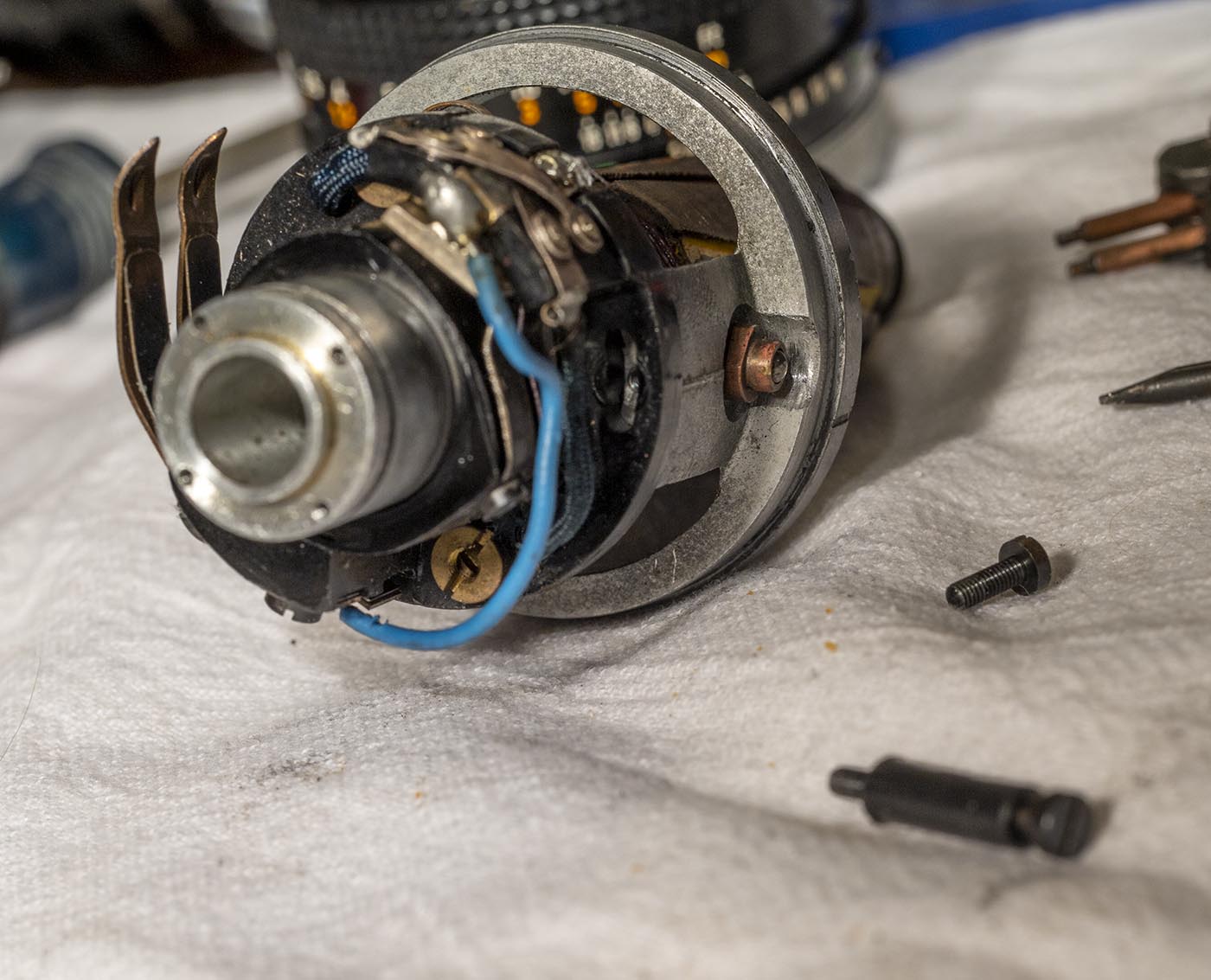
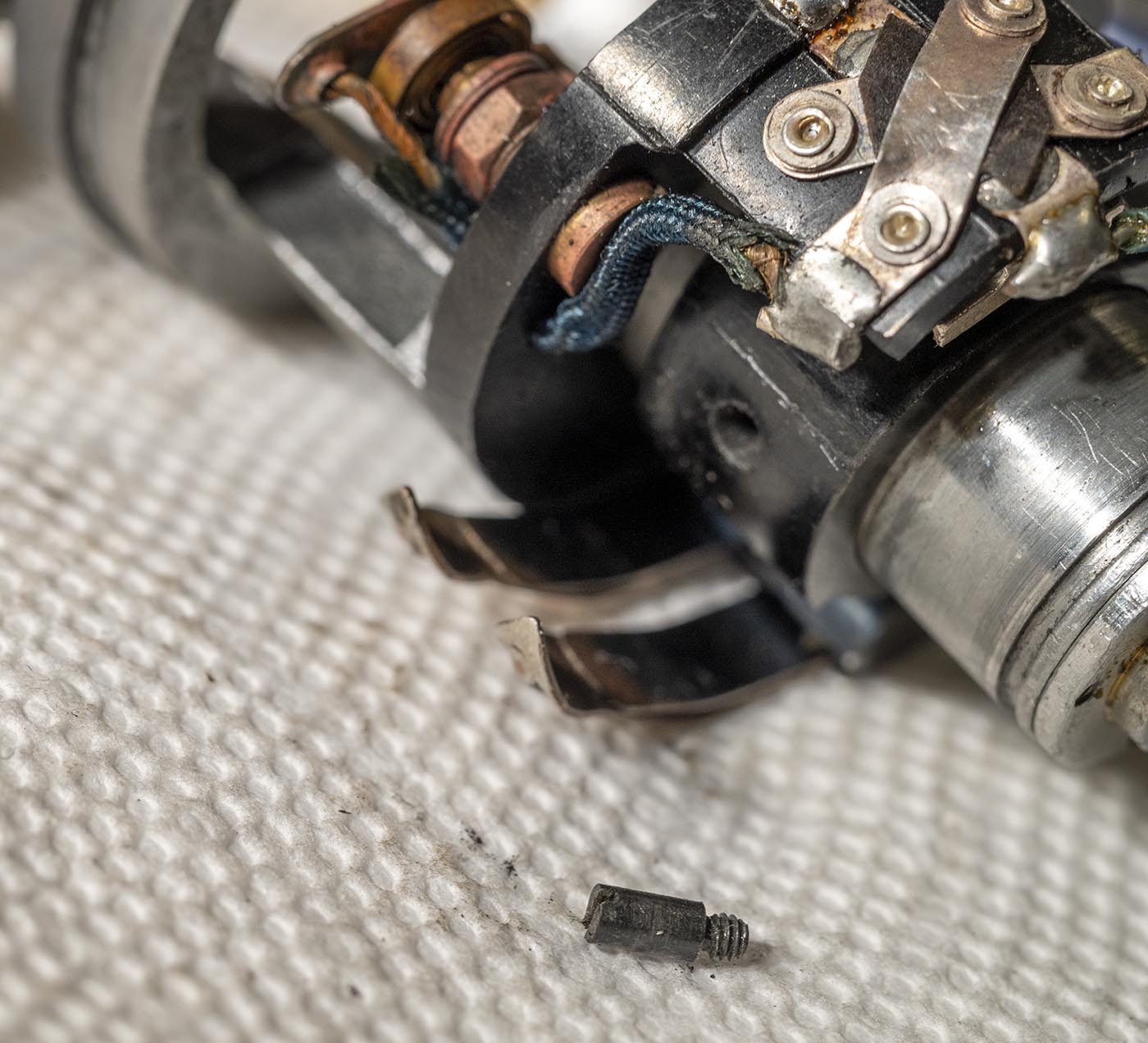
Here is the shouldered screw that keeps the switch actuator piece on the shaft, and limits its travel to the two positions.
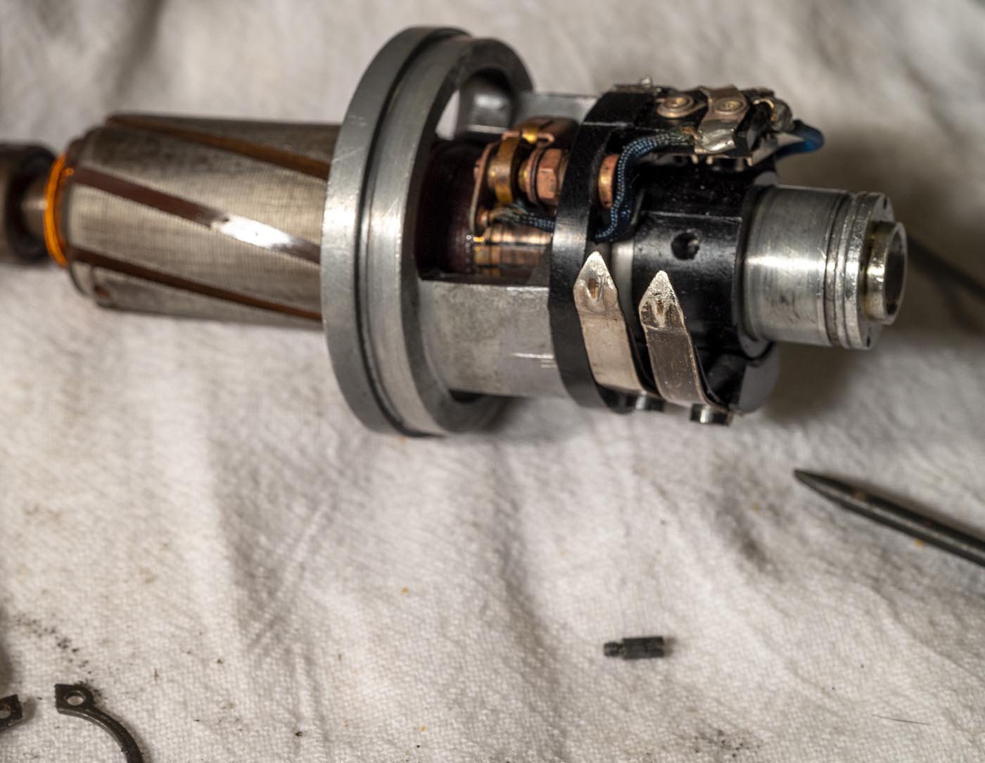
Now, by moving the brushes back out of the way, the actuator assembly can come off of the rear bearing holder piece.
The inner piece comes out of the outer piece too.
Brushes look great!
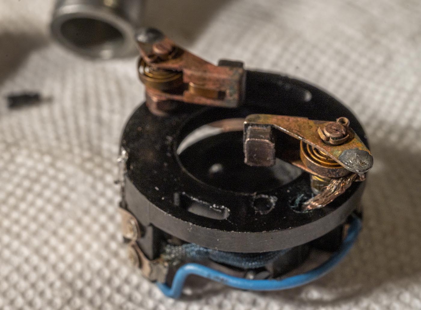
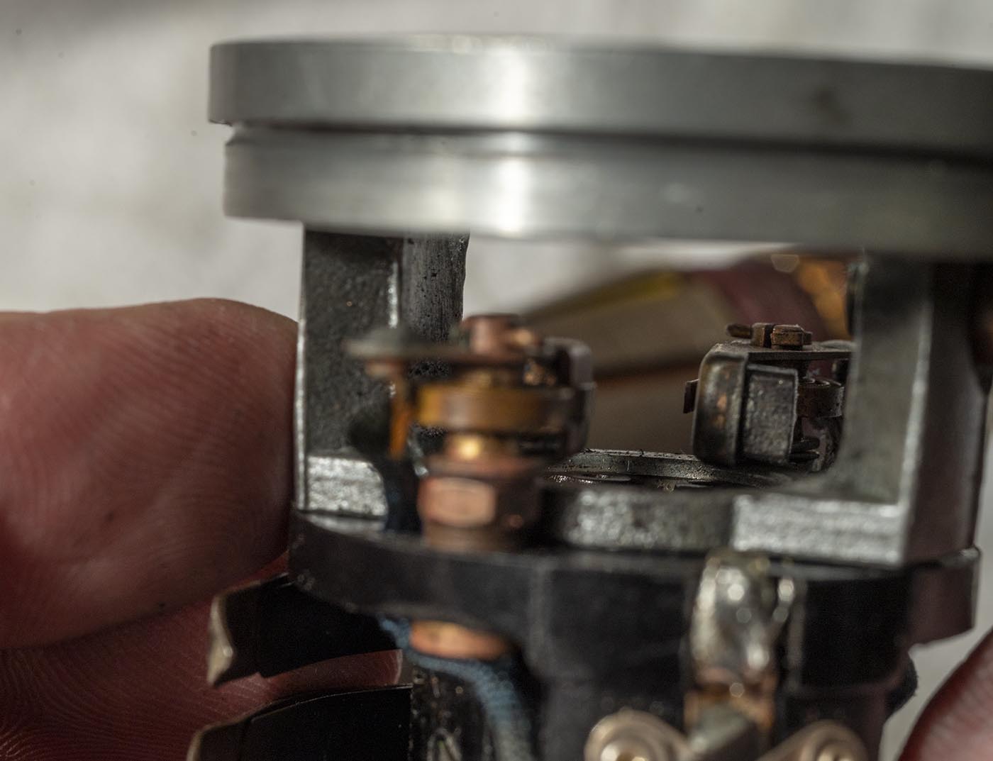
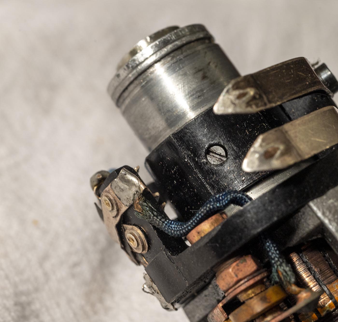
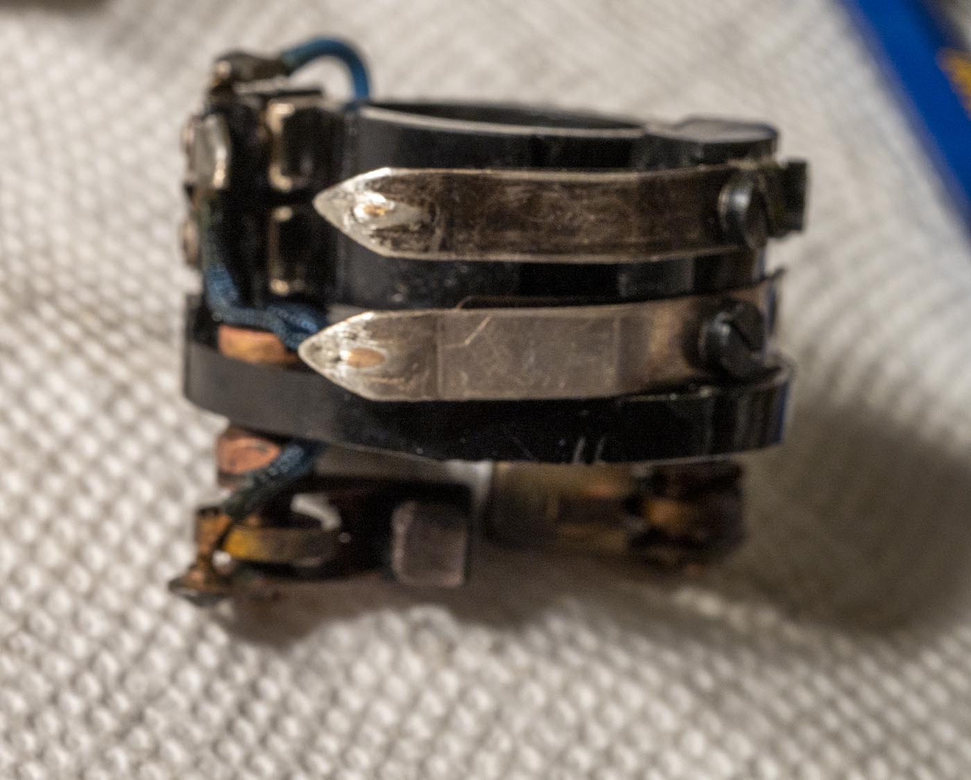
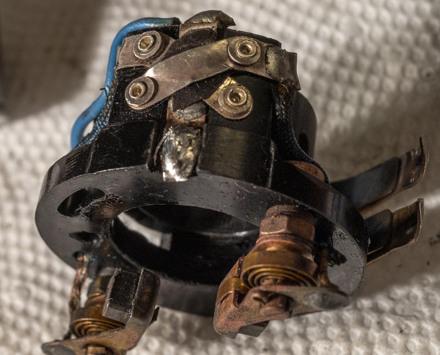
Some detailed shots of the rocker switch for changing directions, and the wiper contacts.
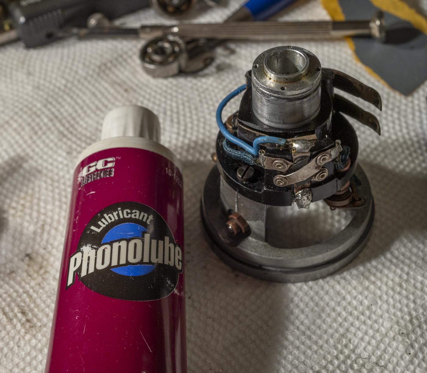
My go-to lube for mechanical assemblies in old electromechanical devices - I put a little between the two tubes before reinsertion.
New bearing installed. The ones I got had buna-N shields/seals instead of metal, but they are permanently lubed and fit precisely.
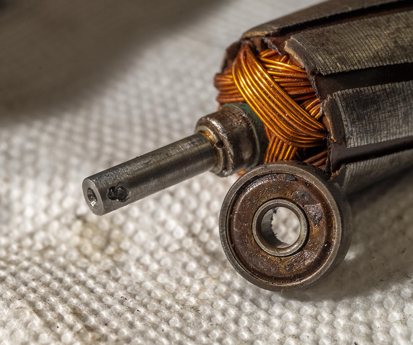
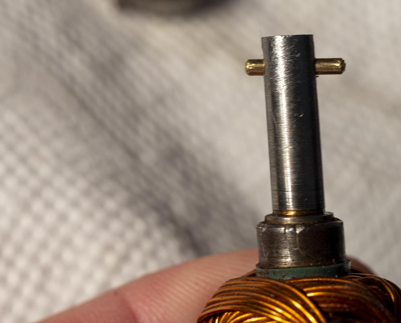
This may be one secret to how the pin stays in/is so hard to remove. That hole is not drilled straight through the shaft, it's at a bit of an angle!
I used 1/16"x1/2" brass dowel rods for this. Not quite as tight as the original steel, but seems to hold just fine. Perhaps marring up the surface a
bit before insertion would make the fit even tighter, but I just went with the snug fit as-is. In operation it can't escape anyway because of the
rubber drive coupling it runs in.
When I went to reassemble it, the white wire was catching on the armature - it had popped loose from its potting material (epoxy) that holds it out of the way.
I mixed up a little JB-Weld (epoxy) to fit it back in its original groove and hold it there, out of the way.
So those wiper contact screws couldn't be tightened down again, because, you know, threads in Bakelite. Terrible idea. The original machine screws are 2.2mm x 4.5mm.
I bought some 2.5mm x 5mm screws, and some 3mm x 5mm screws, and the taps to go with them (flat bottomed taps for blind holes).
The 2.5mm screws are the exact same thread pitch as the 2.2mm ones, so that was the easiest tap in the world to run down there - I simply filed down the 5mm screws
to 4.5mm and it worked! But by the time I'd run the screws in and out a few times trying some stuff, those threads fell apart again too. So then I tapped them out to 3mm, and
filed those screws down to 4.5mm too, and those held. I bought narrow-head screws to fit within the width of the bakelite channel. The 3mm ones had pretty tall
heads though, so once installed, I filed those down a bit to make sure they'd not foul the copper insides of the variable knob. Oh and of course I had to drill
out the holes in the contacts and spring backers to 3mm. The end hole on each already was 3mm, but the middle one on each needed drilling.
I also did my usual trick when working on old variable resistors - you kink the contact a tiny bit to the side, to have it run on a new track on the resistor wire.
BAD IDEA!! Those slots in the copper inside the speed knob are not very much wider than the contacts, and if the contacts touch the outer copper instead of
the resistor wire, the motor stops dead. The wiper contacts need to be straight and level and true. So I say again, just leave them alone! You'll be much happier in the end.
I eventually got them back where they belonged and now the motor works quite well. (When I got it, it was noisy and the speeds were erratic as you spun the knob.)