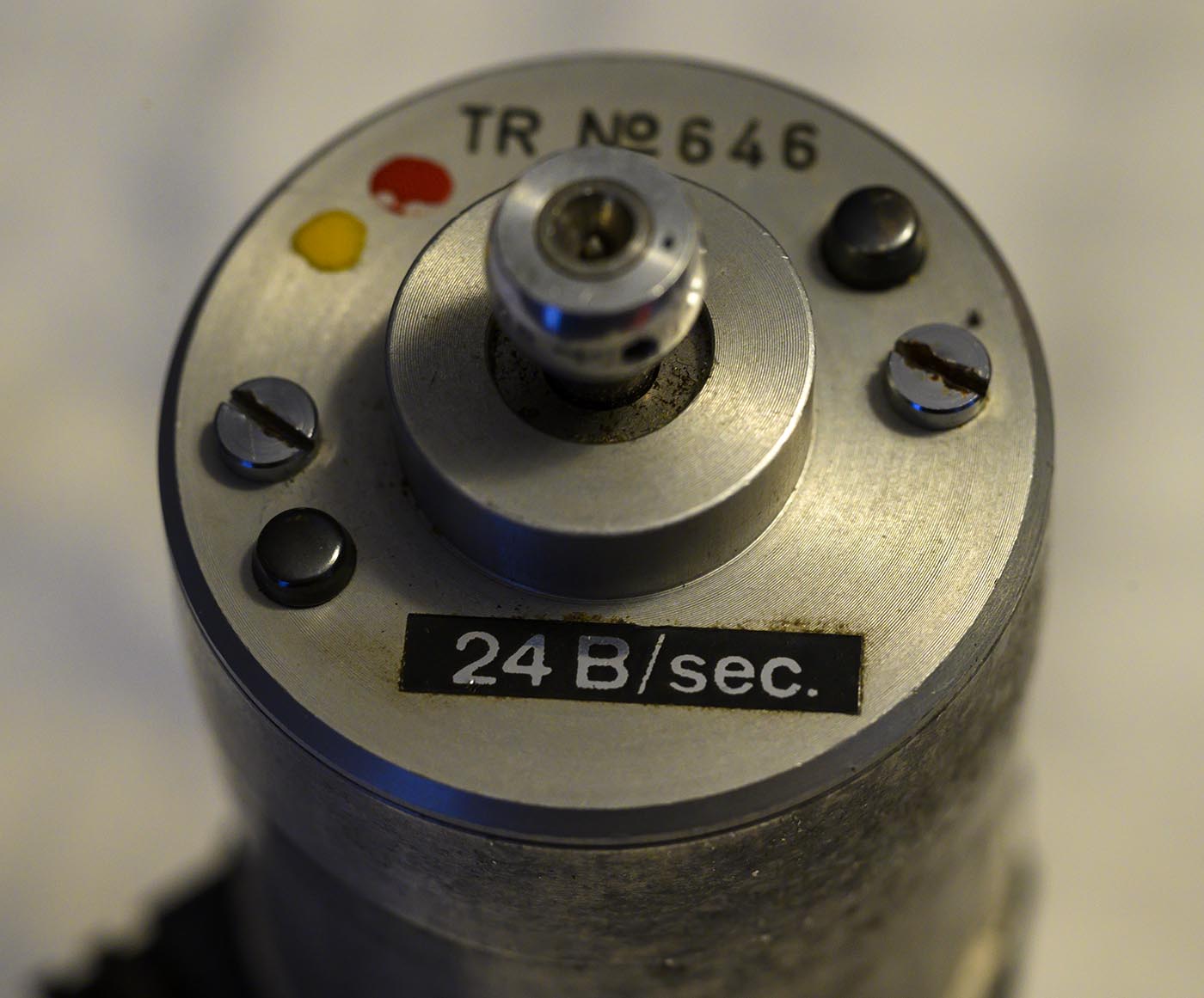
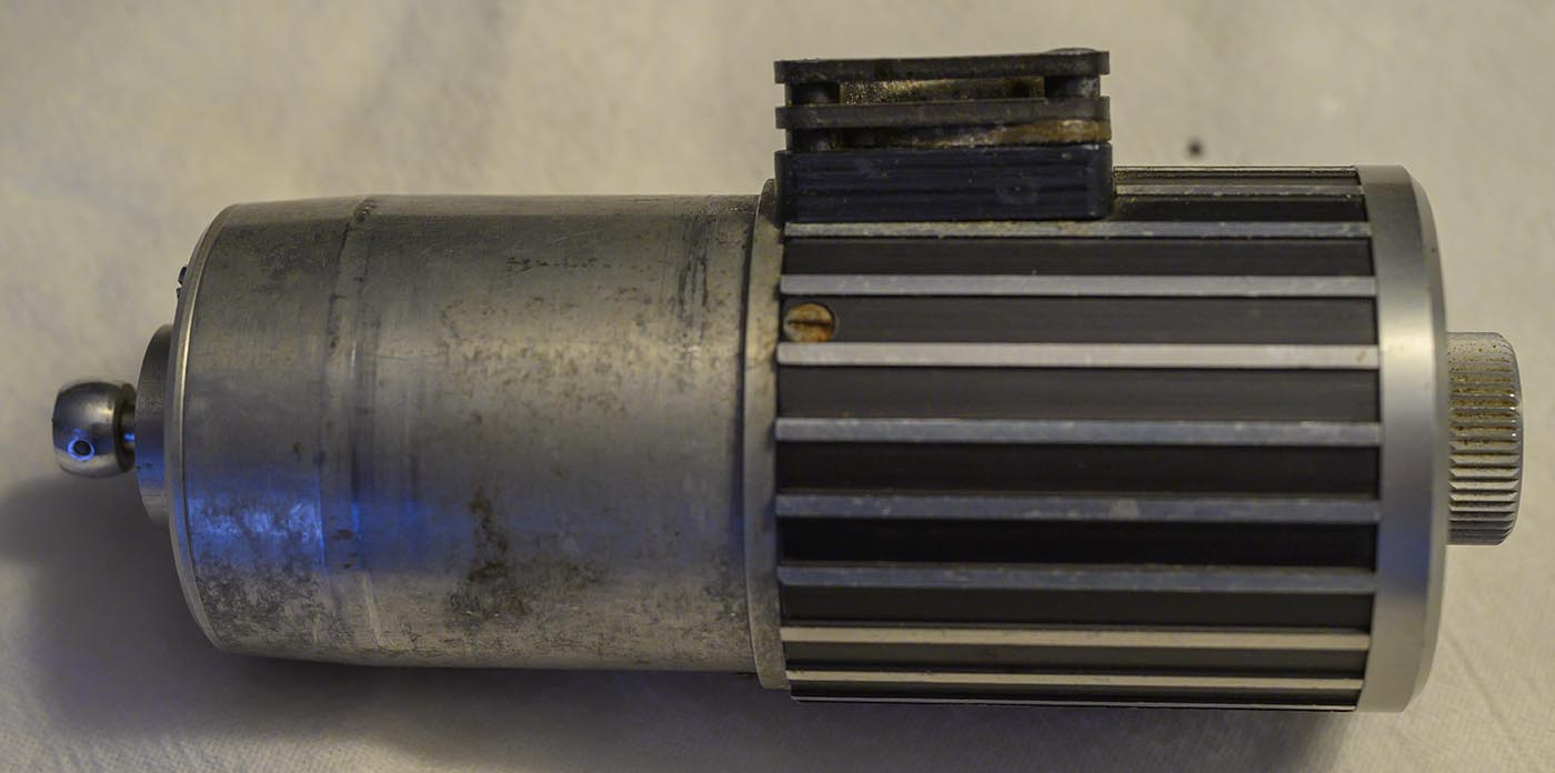
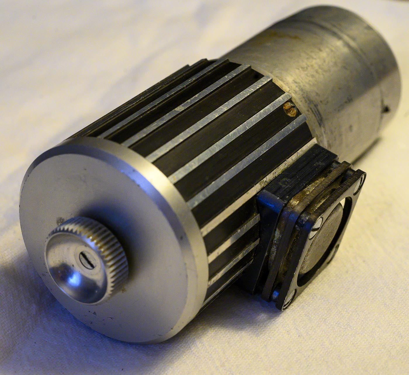
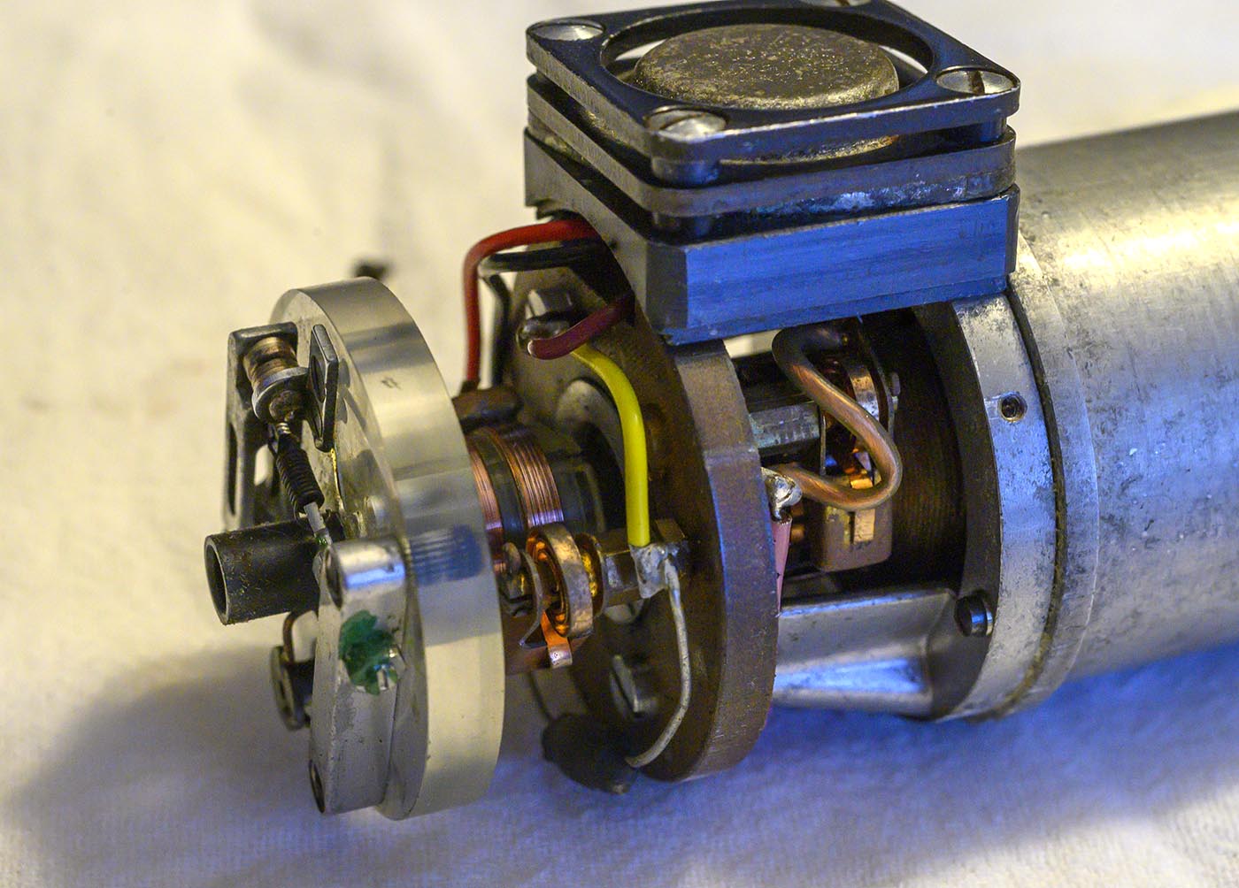
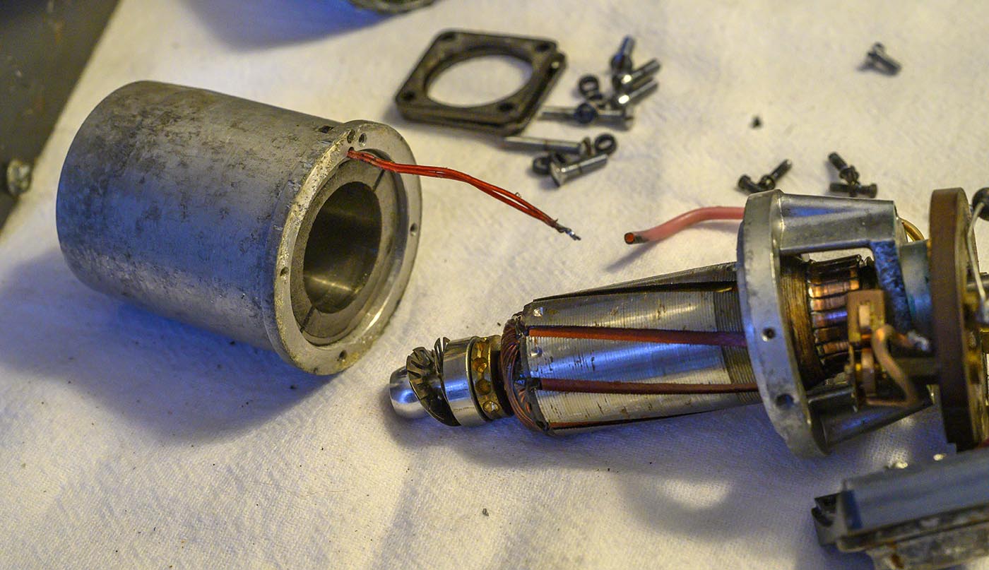
Let's tear down an Arri 16S constant speed motor and see what's inside. Here are a few shots of the motor before taking it apart.
(Zooming in on it really shows up all the age related corrosion - it doesn't look this nasty in person!)
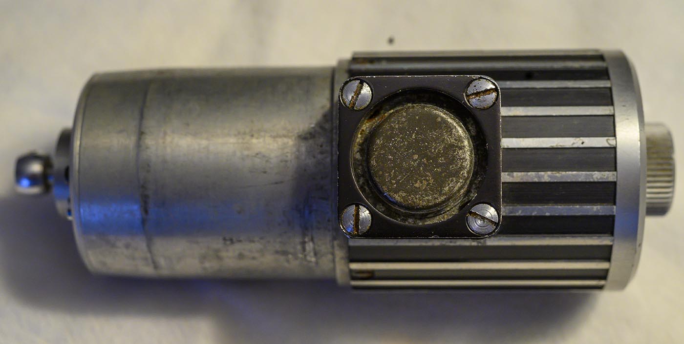
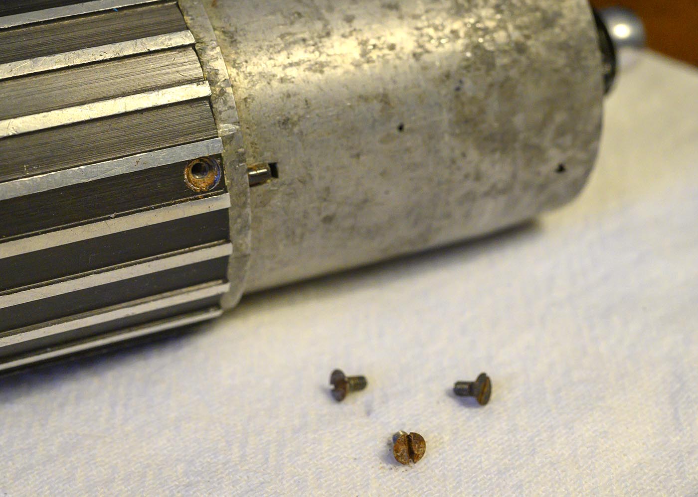
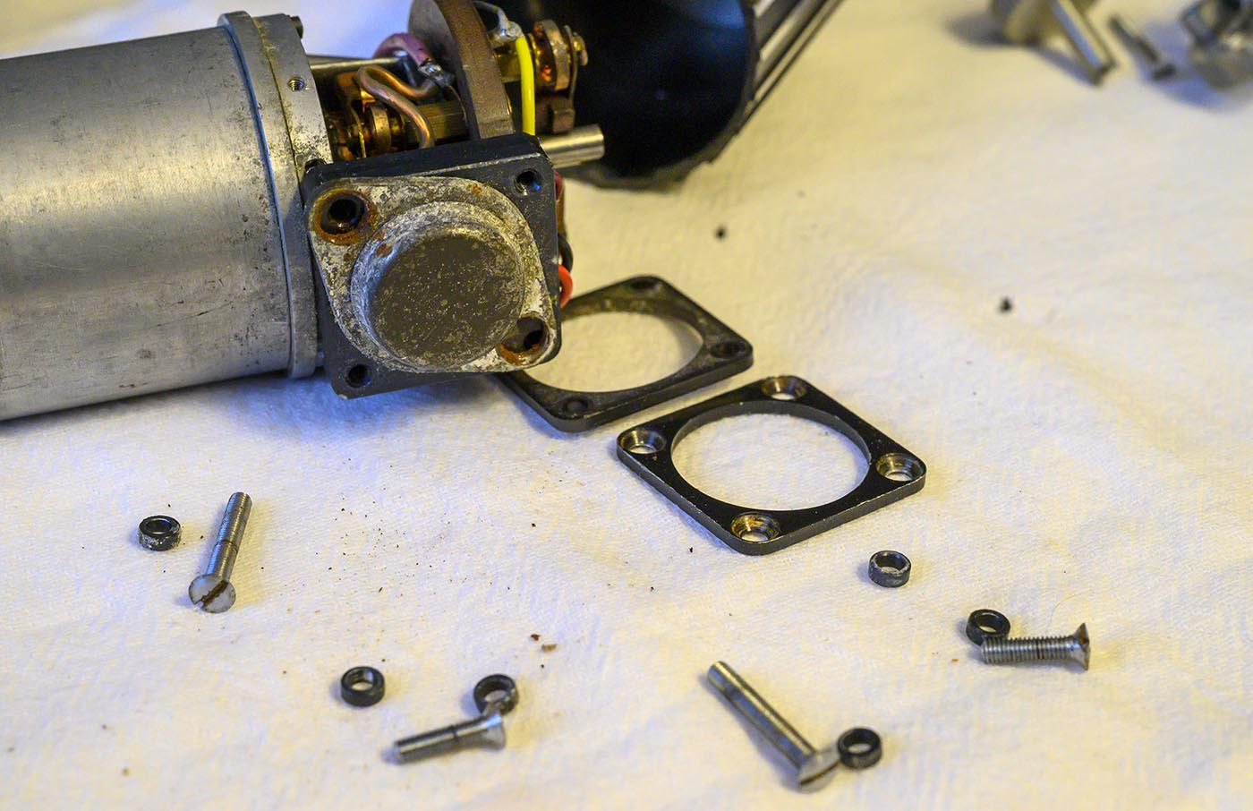
First, we'll take out the obvious screws that hold something together on the drive end...
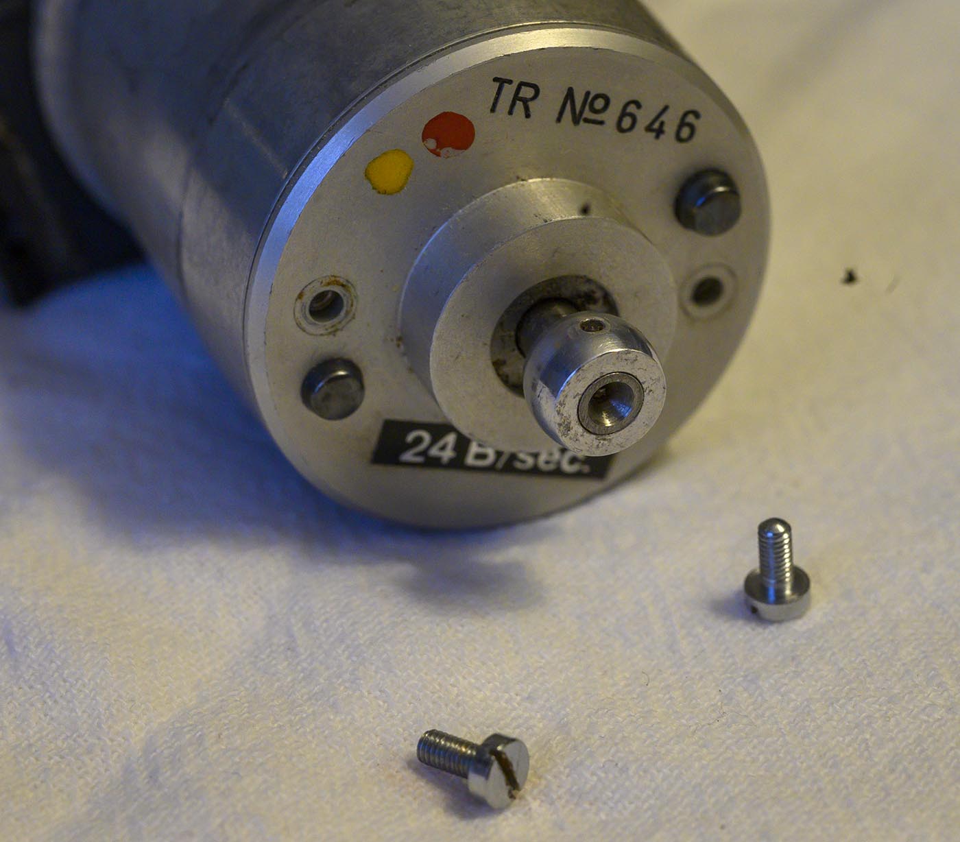
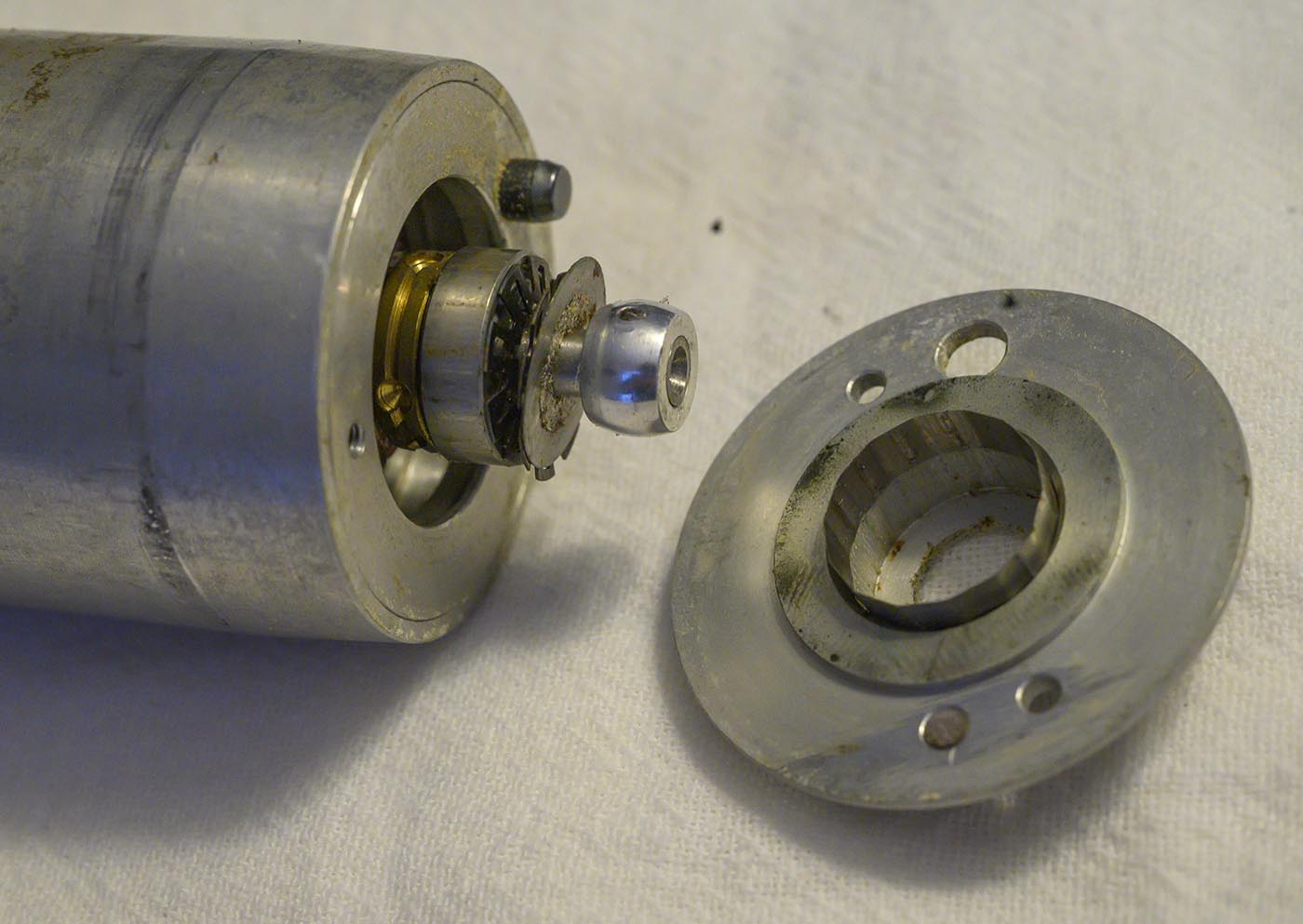
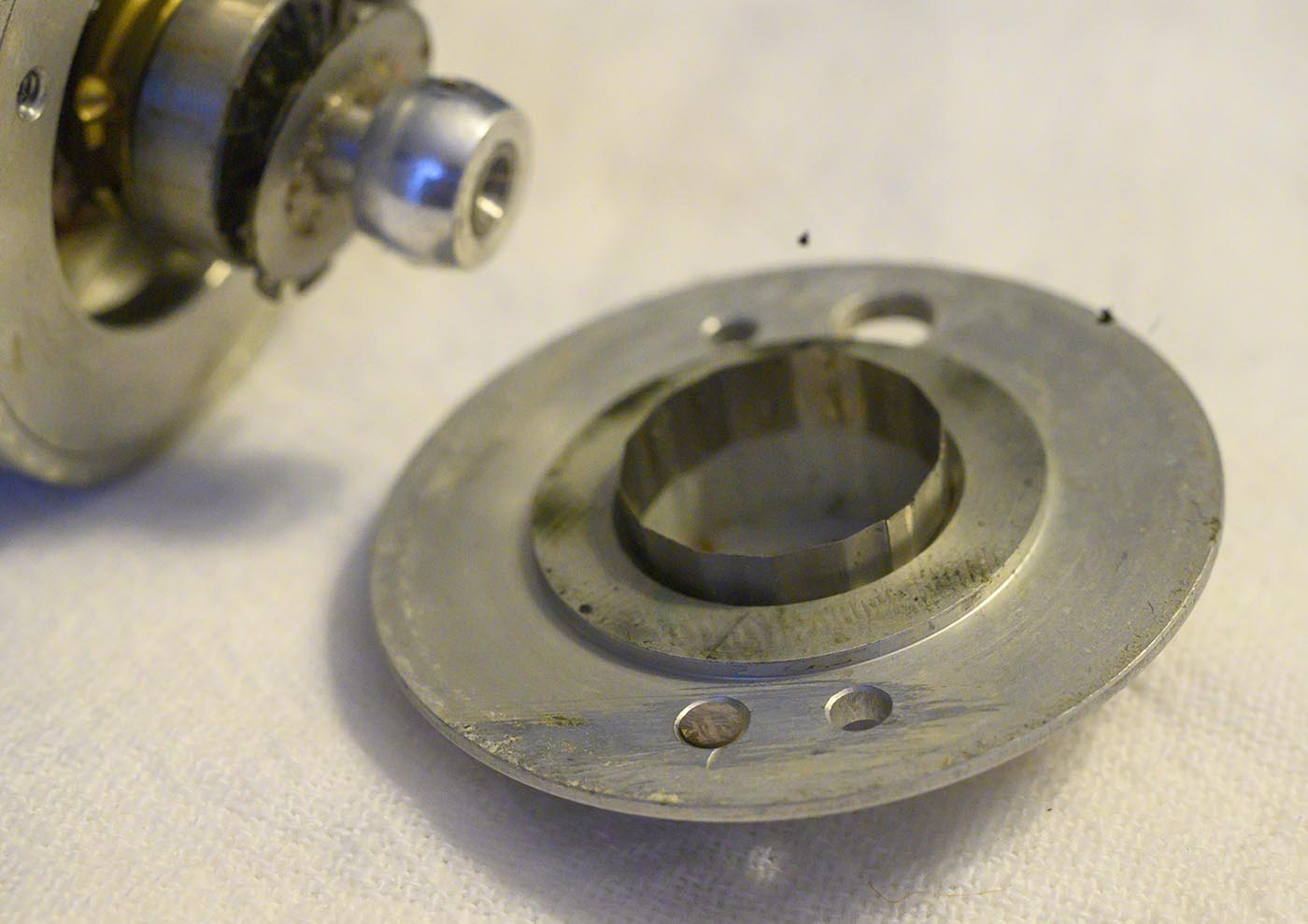
Turns out it's just an end cap to hold the bearing on that end. Note the shim to hold the bearing in the cap, I guess to make it easier to get apart and back together
rather than having it pressed in? Also note the dust shield and spring plates that keep it pressed against the outer shell.
Well the next most obvious screws are the three around the perimeter of the center, we'll take those out.
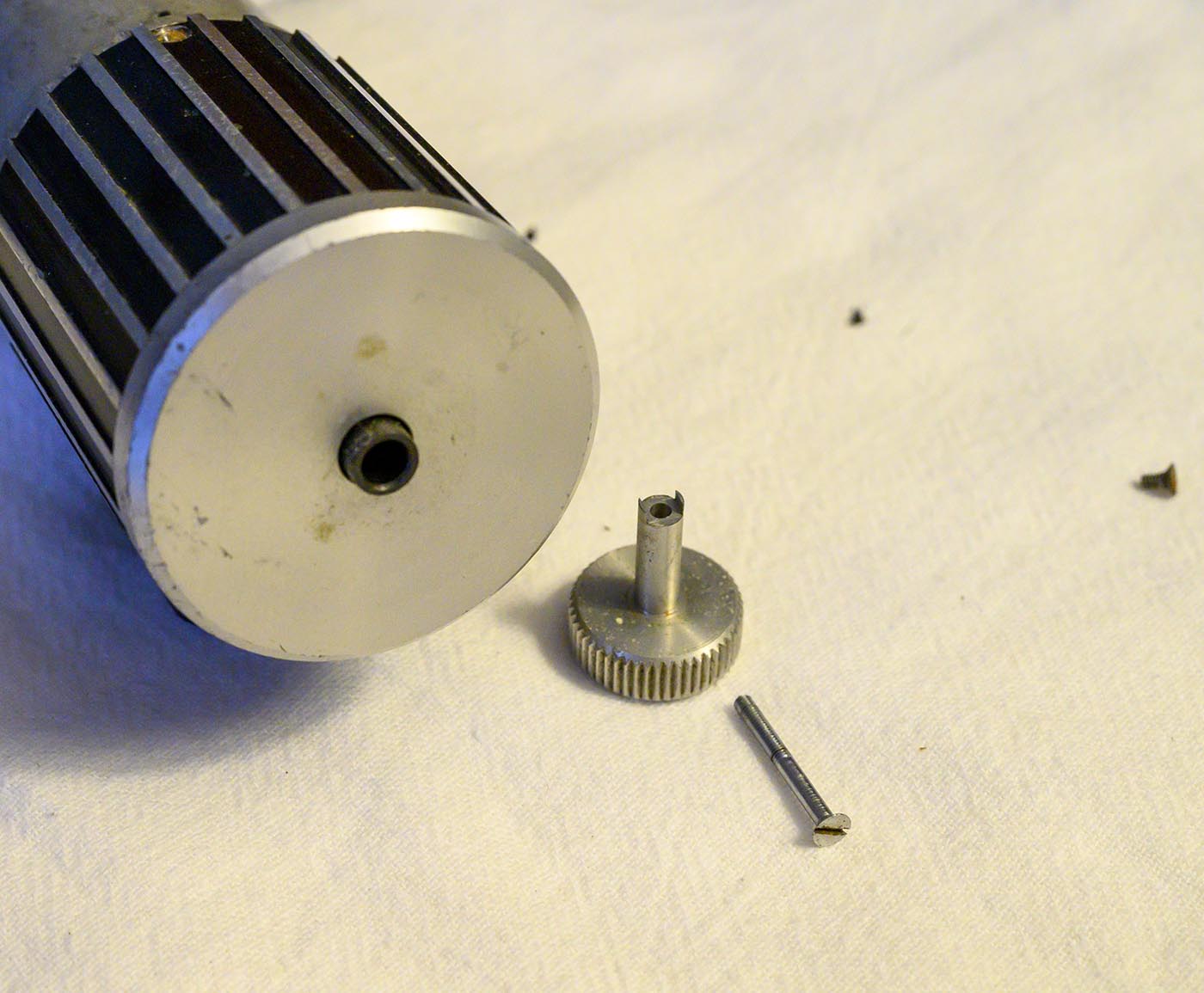
Whatever comes apart with those screws out isn't going to happen until we remove the knob though.
OK, it's just a cover shell for all the really interesting guts of the motor.
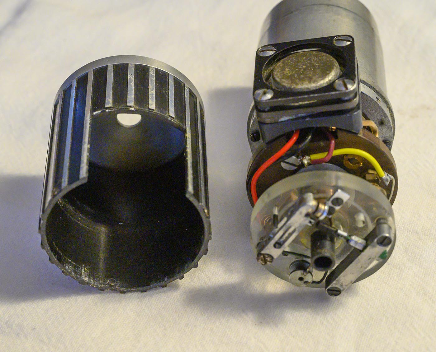
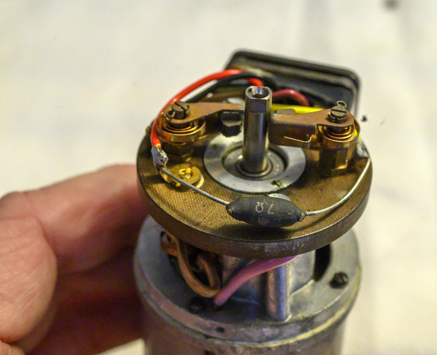
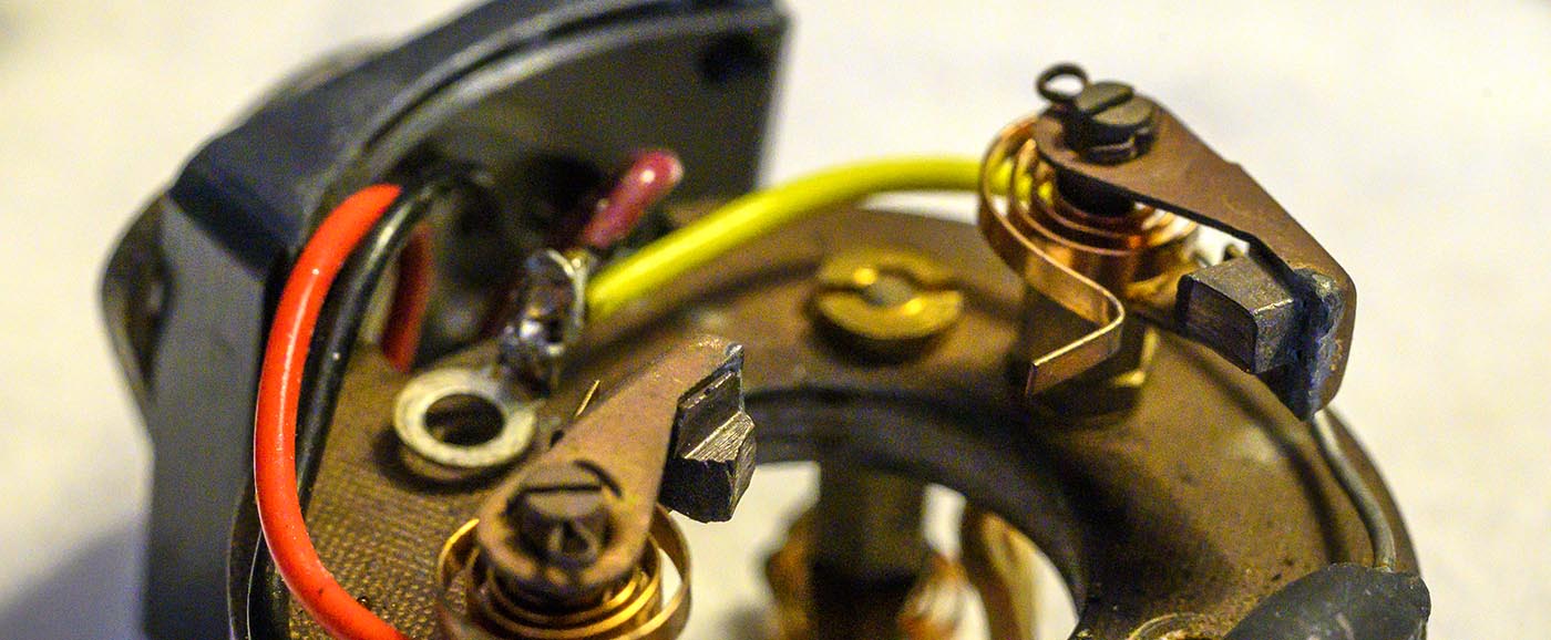
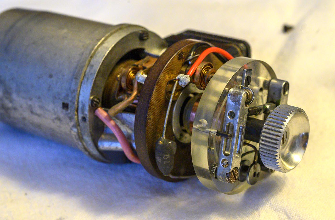
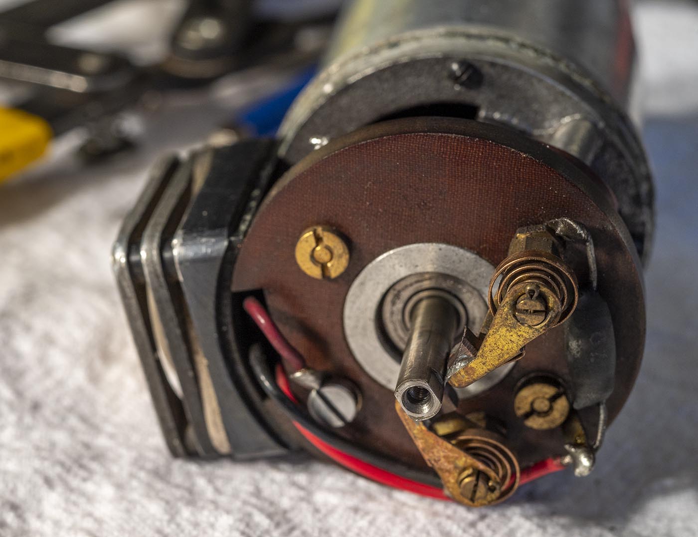
The normal motor brushes are kind of buried in there, but behind that is some kind of governor assembly with another set of brushes.

The governor assembly just falls off without the knob to hold it on.
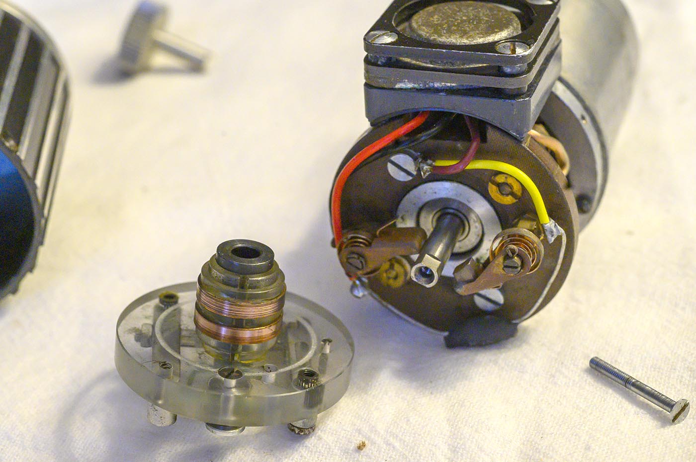
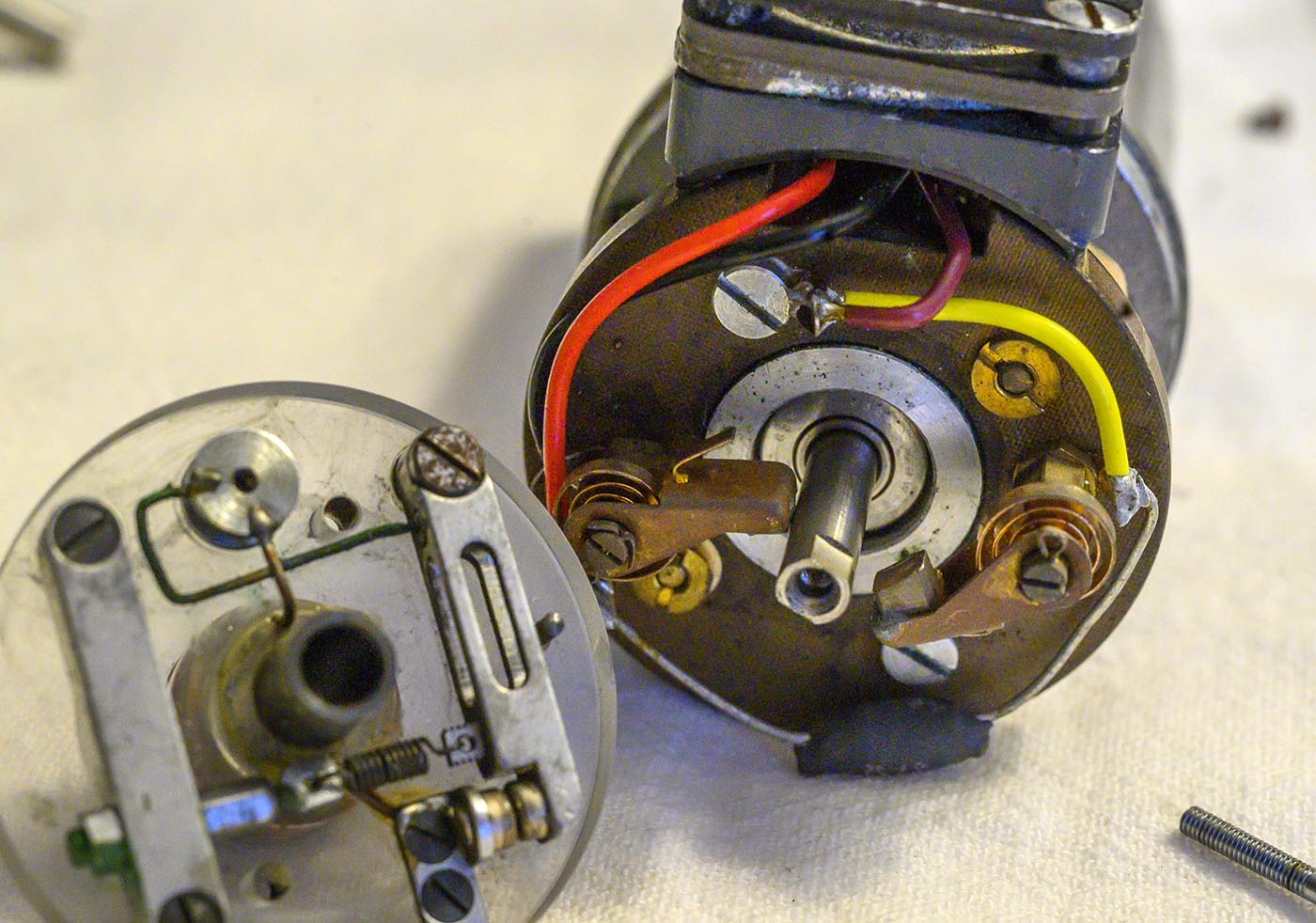
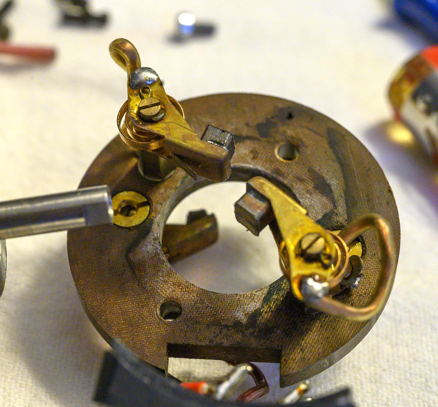
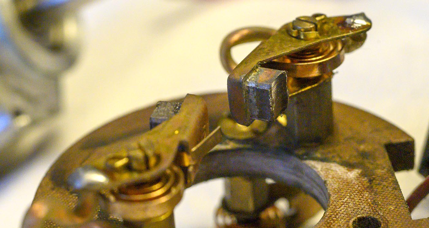
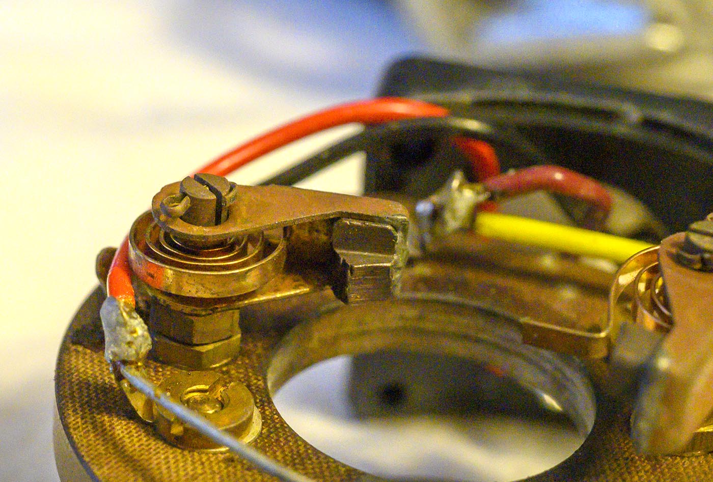
We can see it's some sort of electromechanical governor. When it spins fast enough, the weighted arm will pivot out, disconnecting the electrical contact.
Then it will slow down, restablishing contact, which will make it speed up again, and so on. There seems to be a spring and an adjusting screw involved.
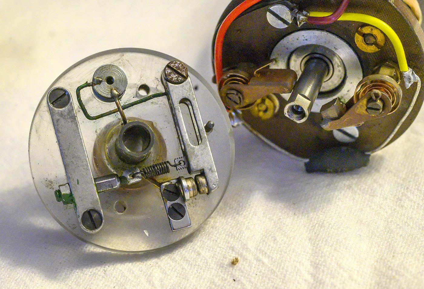
The brushes in this case just get the motor power out to the governor and back, so they're not as complicated as normal motor brushes and armature contacts.
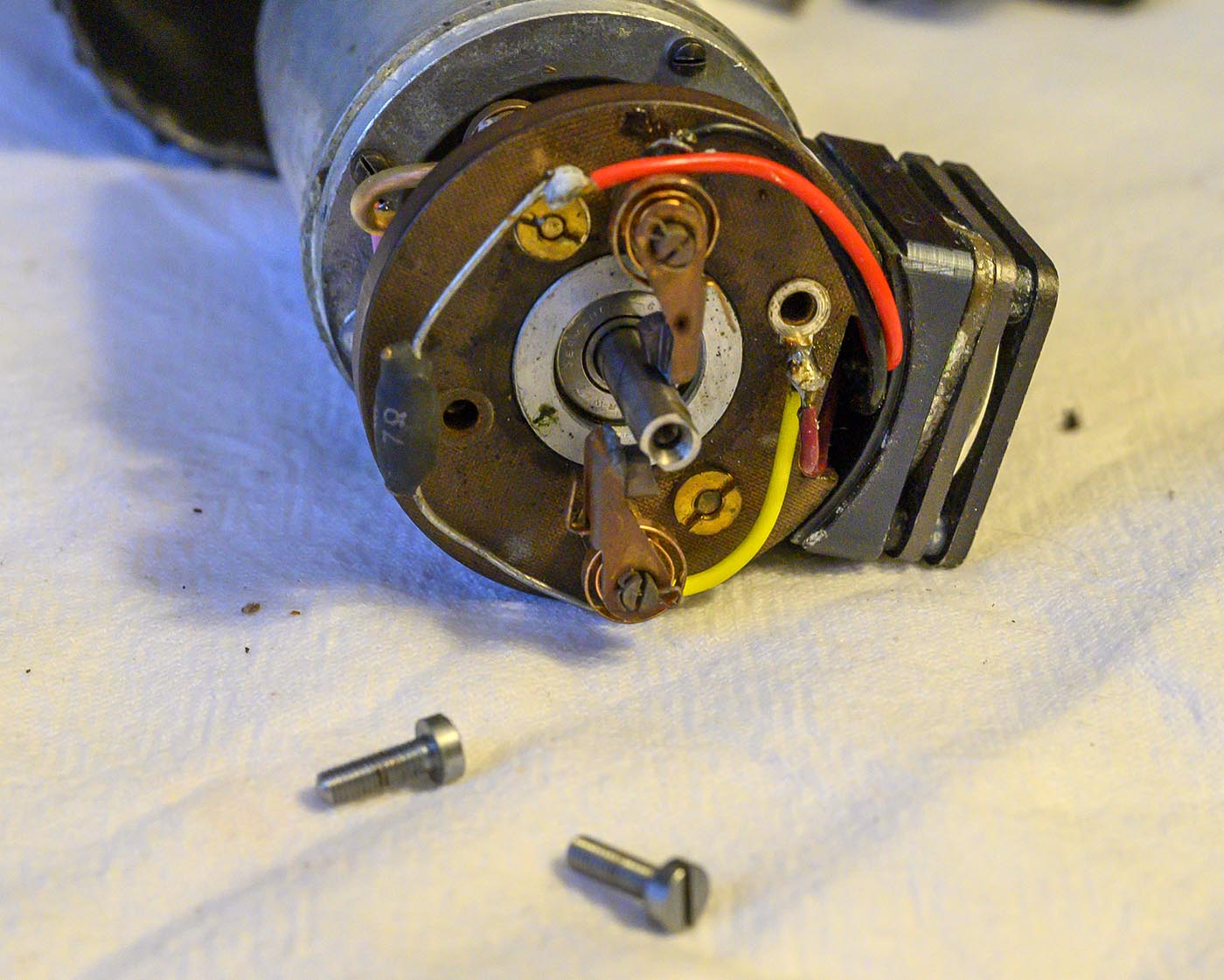
There's also a 7 ohm power resistor in the circuit. I bet that helps snub arcing across the contacts.
Trying to get a good shot of the bearing number. Failed here, but I'll get it later. You can see how the bakelie plate is used to hold all these brushes and things.
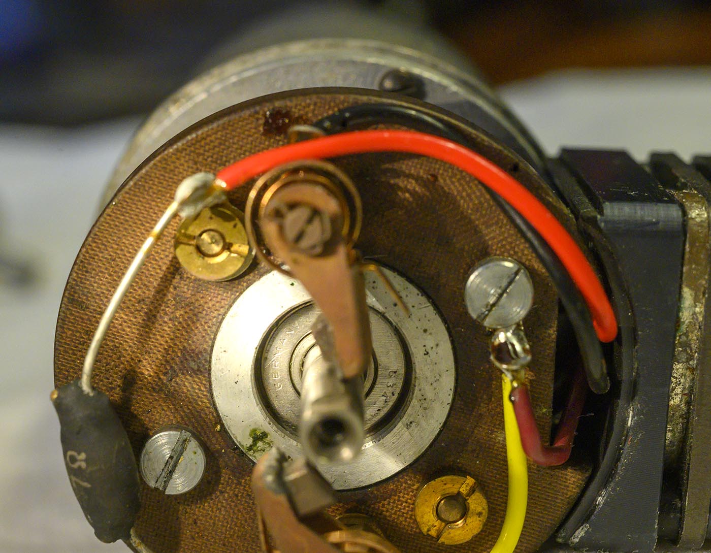
Farther in we go! Two screws hold the bakelite plate on, and secure an eyelet used to join two wires together (also grounding them, presumably.)
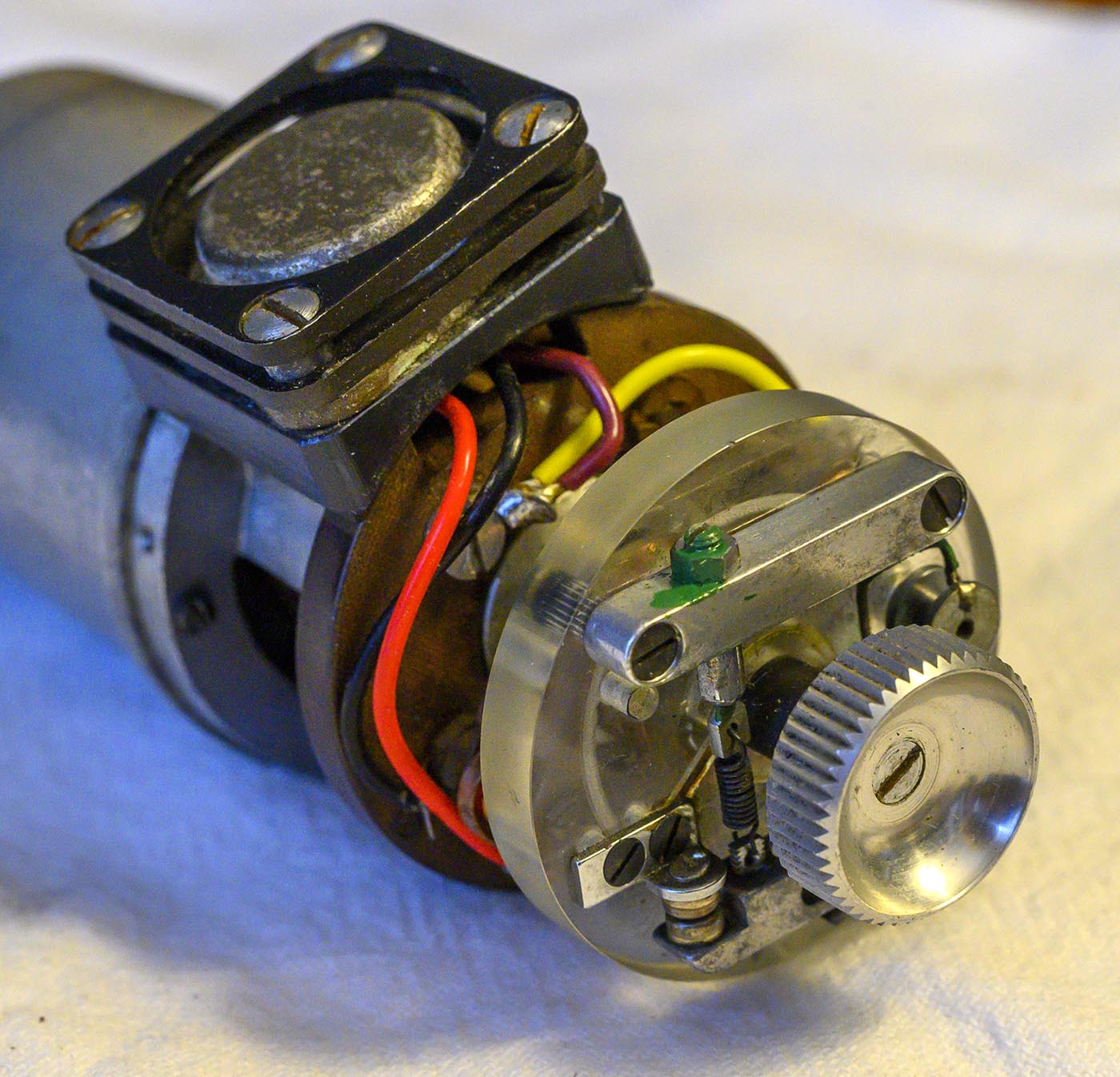
Out come the screws that mount the power transistor and heatsink to both the bakelite plate and the motor body, because we're not getting them separated otherwise!

On each side, a short screw goes through the two thin heatsink plates, with a spacer in both the gaps, and into the thick transistor mounting plate.
And then a long screw goes through both plates AND the base and screws directly into the bakelite plate on one side, and the motor end cap on the other.
Only one spacer goes in each of the long screw sides, because the power transistor itself fills the gap between the middle heatsink plate and the mounting plate.
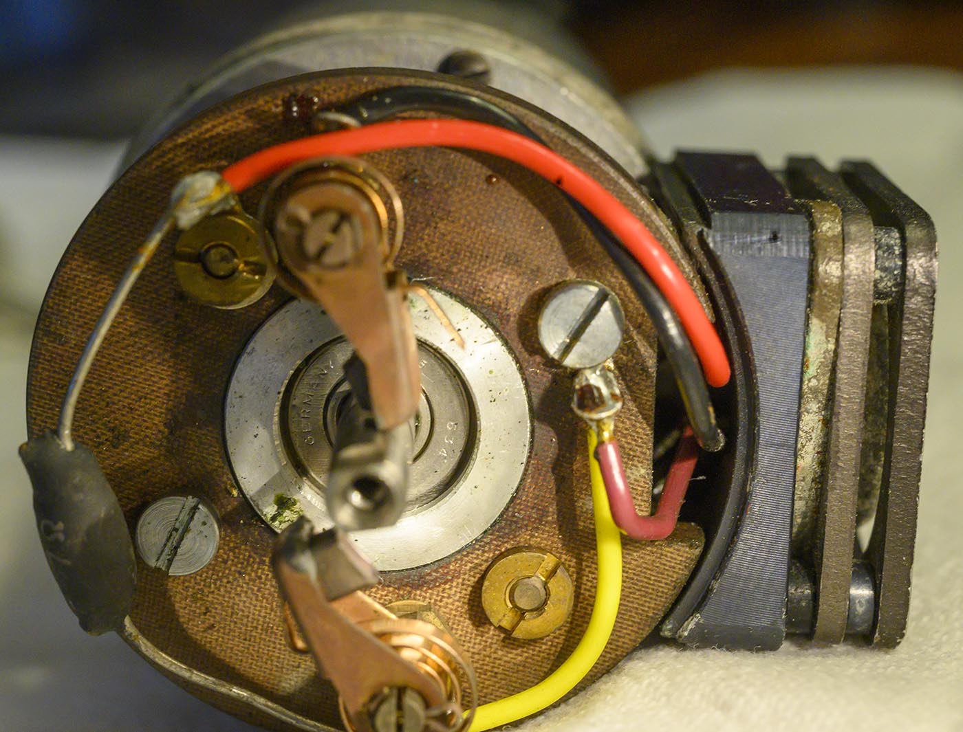
Next I took out the 4 little screws that seemed to hold the rear mounting plate structure to main body of the motor. This would have been easier if I had removed the Bakelite plate
first but I hadn't fully understood how things come apart yet. With these screws out, the metal parts still won't separate because of the pink wire there.
We need to start by desoldering the pink wire from the brush wire mounting lug (the one under the yellow wire).
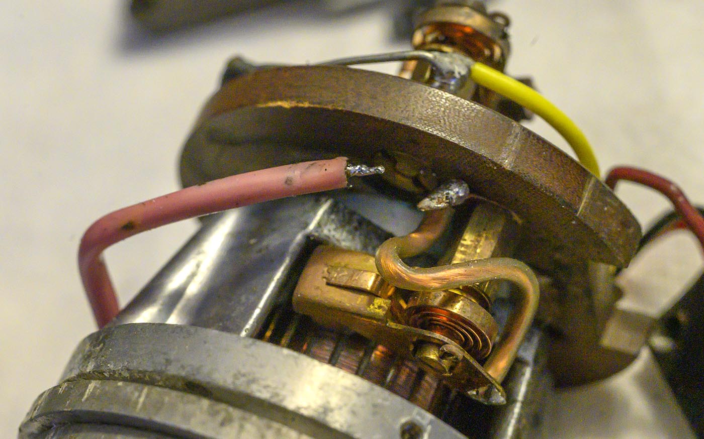
A shot of how the wires connect to the power transistor. It looks like a TO-3 case, but there is an extra lug there, connected to the case.
Subbing a TO-3 part would require soldering to the case, which might be tricky. Original part is a Siemens "AUY-21 (III)" which is getting hard to find directly.
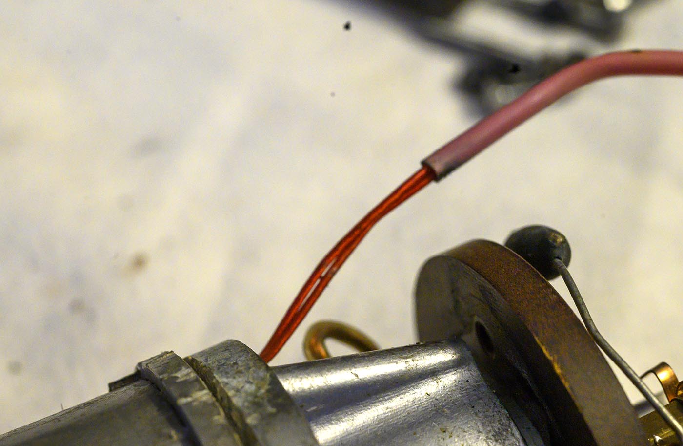
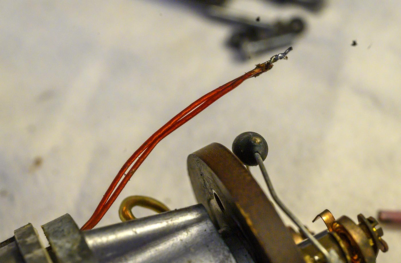
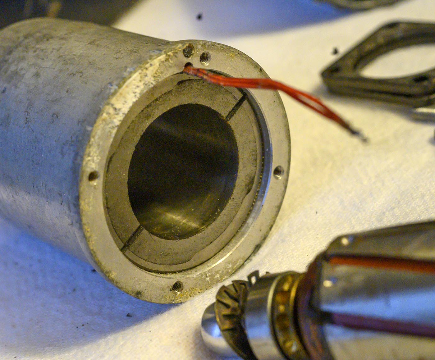
Turns out that pink "wire" is actually pink insulation over a couple of stiff coated wires wrapped together. This would appear to be how they manage to get the wire
threaded through the small space in the case, then the pink insulation just protects it from nicks in the area where it travels fron the hole in the case to the lug.
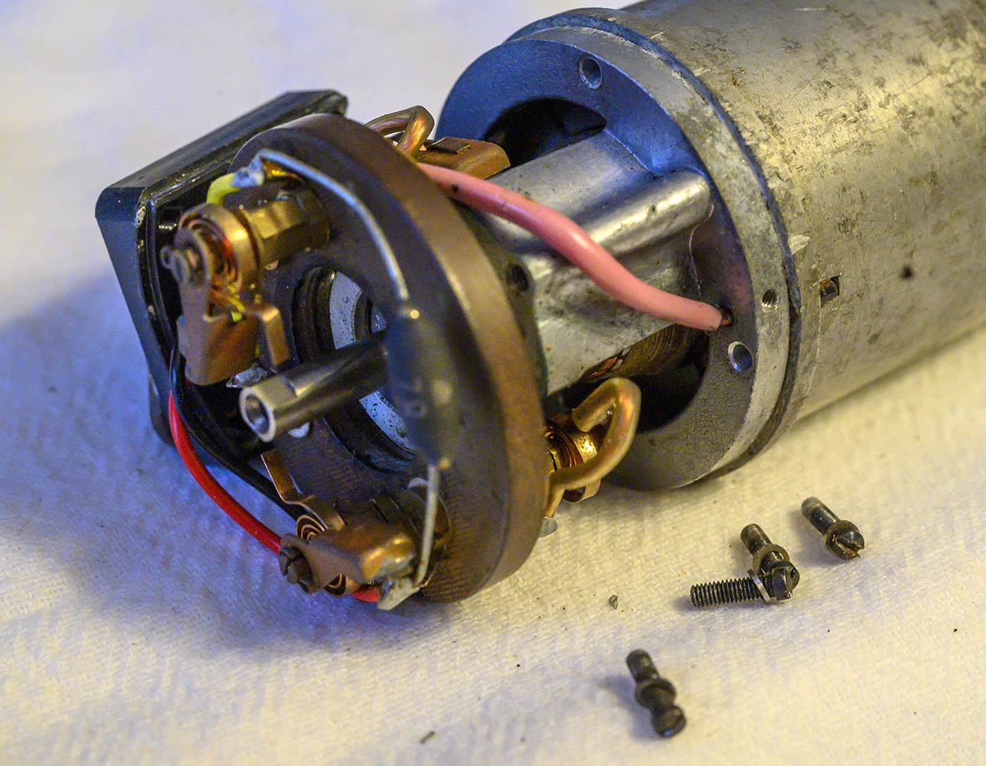
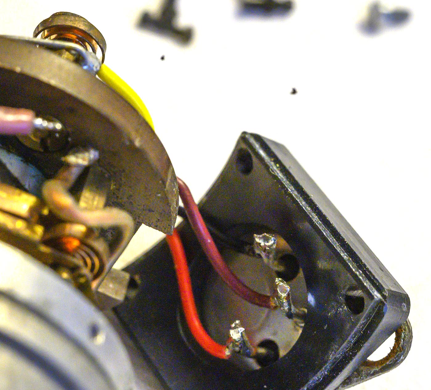
Now we can VERY carefully pull the end cap and bakelite plate and armature away from the main body, as we thread that pair of wires back through the hole in the end cap.
We need to be careful not to let the edge of the hole gouge the coating on the wires. Slow but steady.
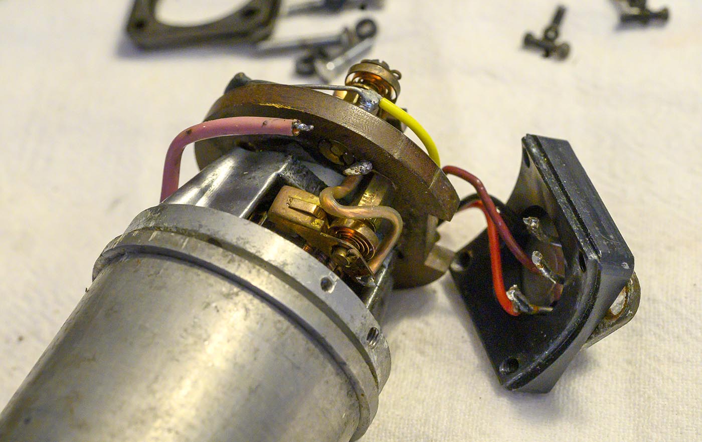
Now we can pull the brushes back and get the whole bakelite mounting plate around and off from the end cap. In retrospect we should have desoldered the pink wire,
then extracted the bakelite plate off the end cap, which then would have gotten us a clearer shot at those 4 screws that hold the end cap on. Then pull the end cap off.
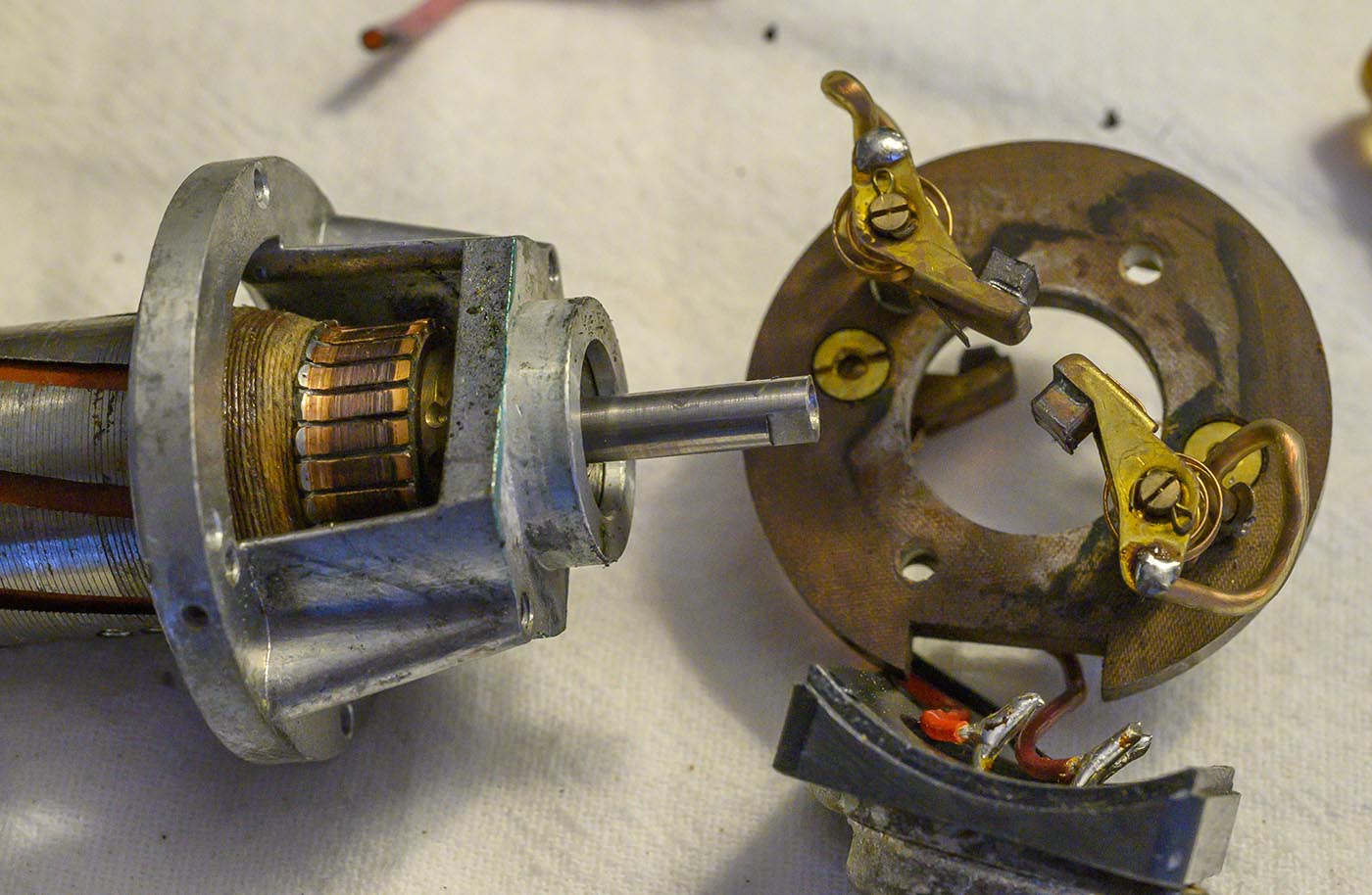
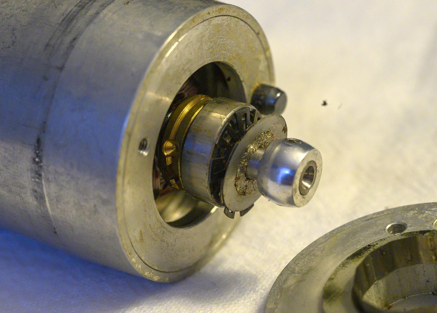
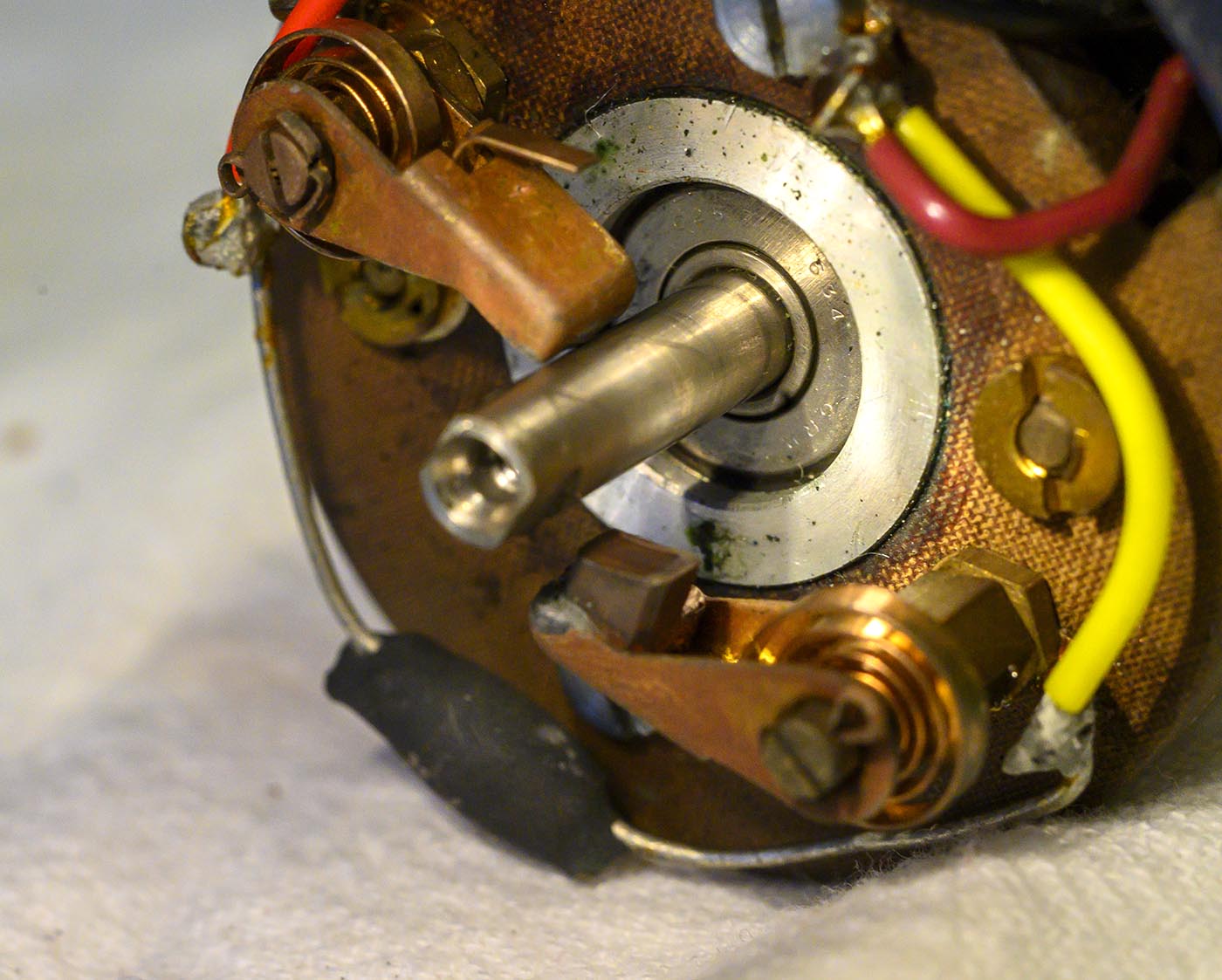
Main motor brushes are actually in pretty good shape!
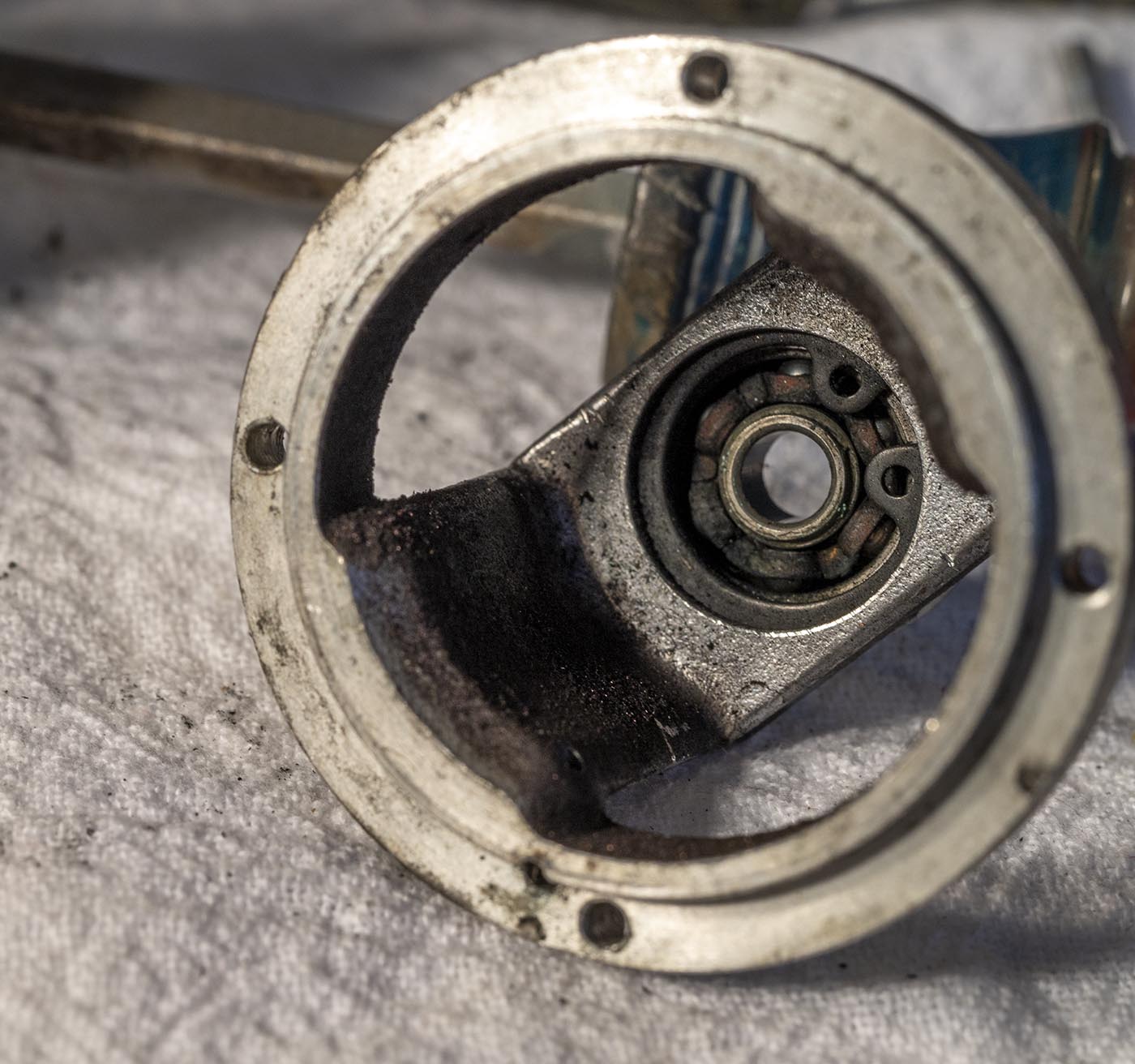
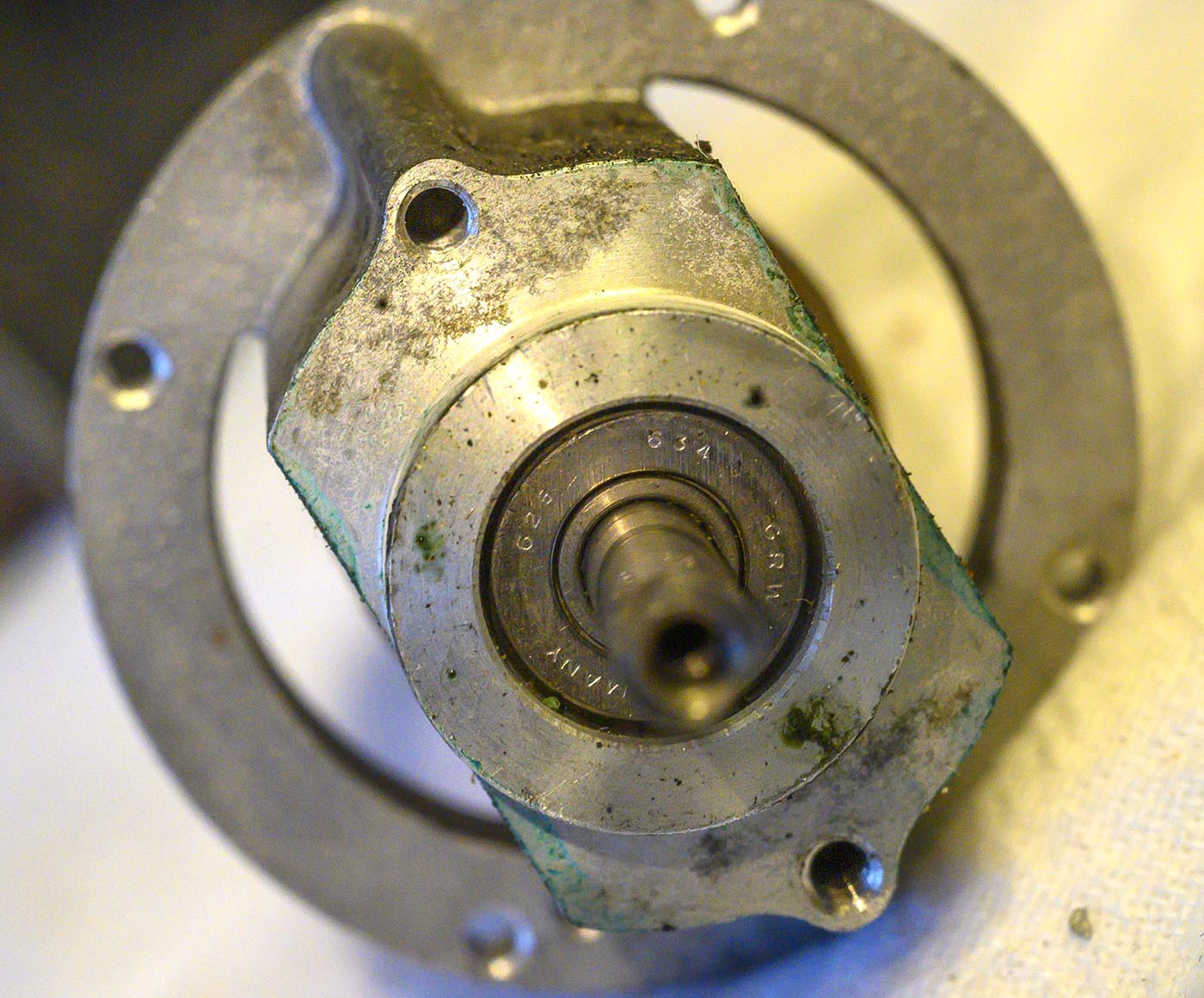
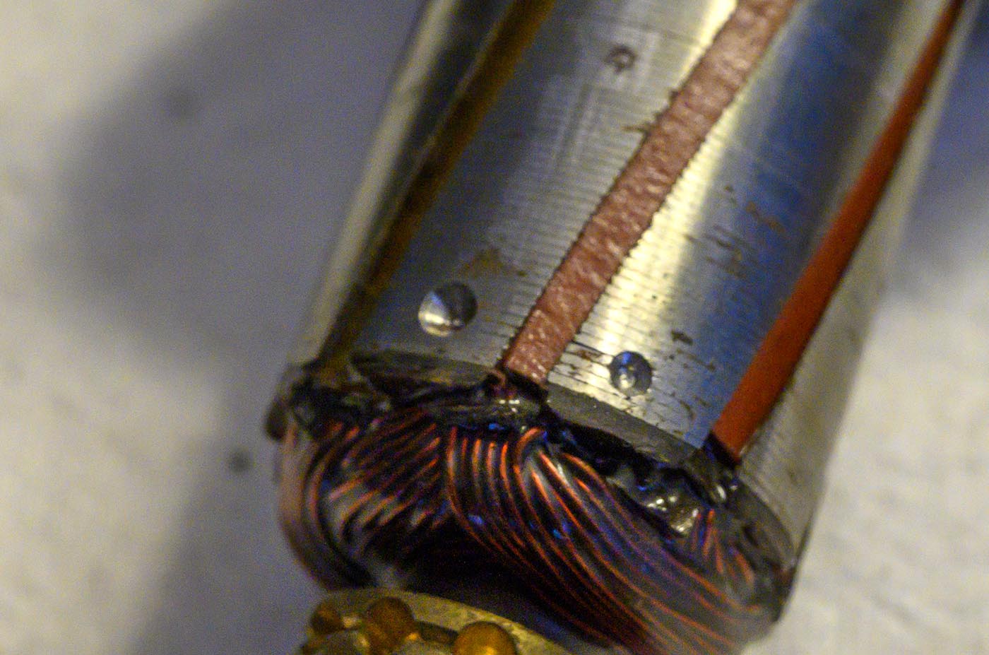
Ah now we can see that bearing number. GRW 625 634. Same bearing is used on both ends. Looking that up in a GRW catalog I'm a little confused. The 634 bearing
has a 5mm shaft hole, which matches what this armature has. But the 625 bearing has a 4mm shaft hole, so why is that number even there, shouldn't it be one or the other?
Both have a 16mm outer diameter and a 5mm depth. These bearings were in fine shape so I didn't remove them for more careful study, as that was a fair bit of extra work.
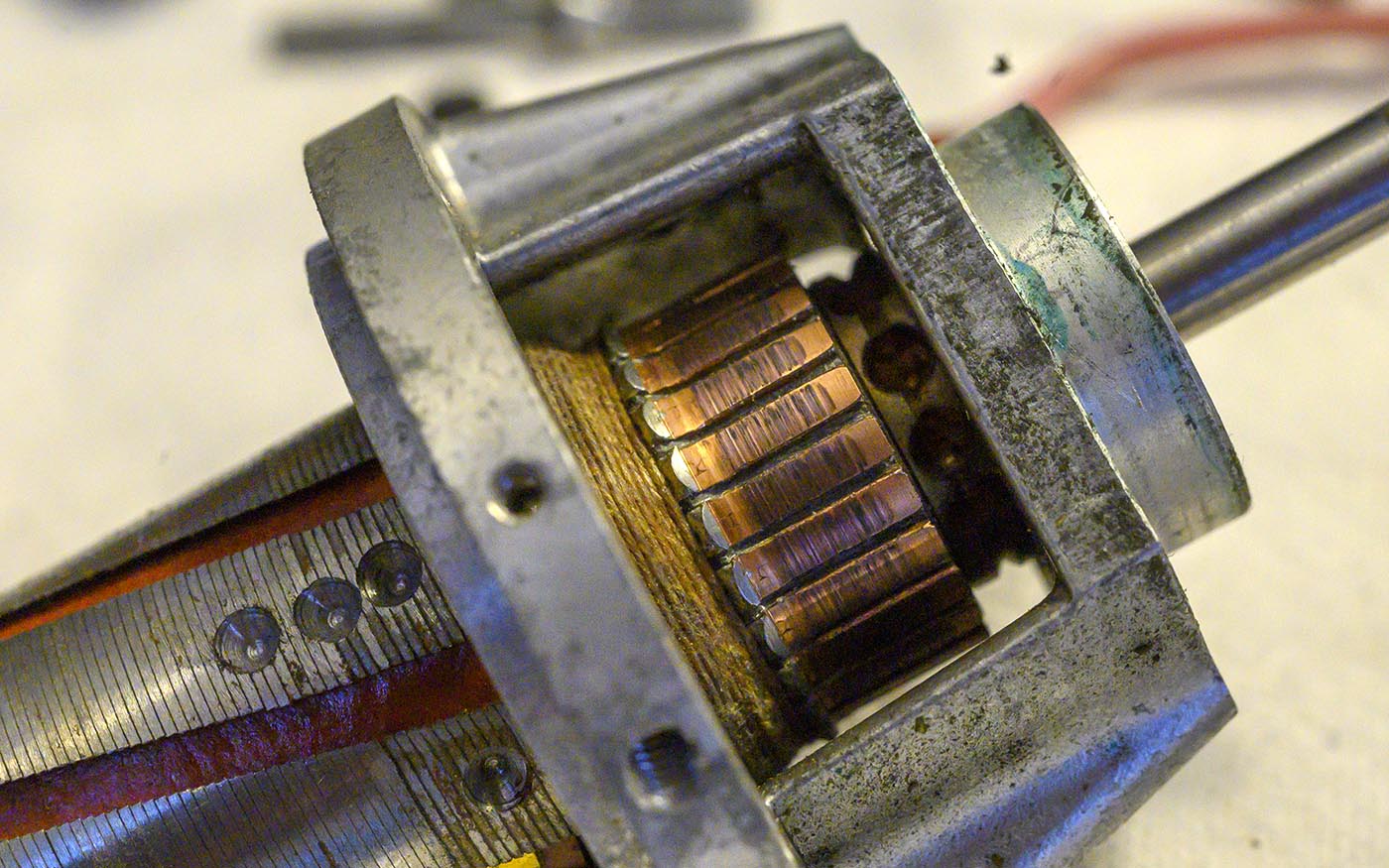
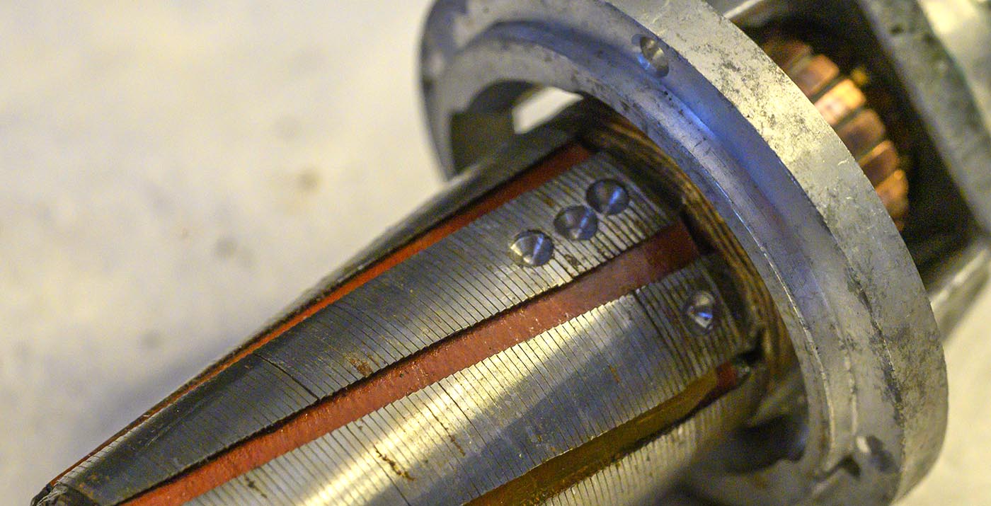
The armature contacts are pretty pitted, we'll sand those down later.
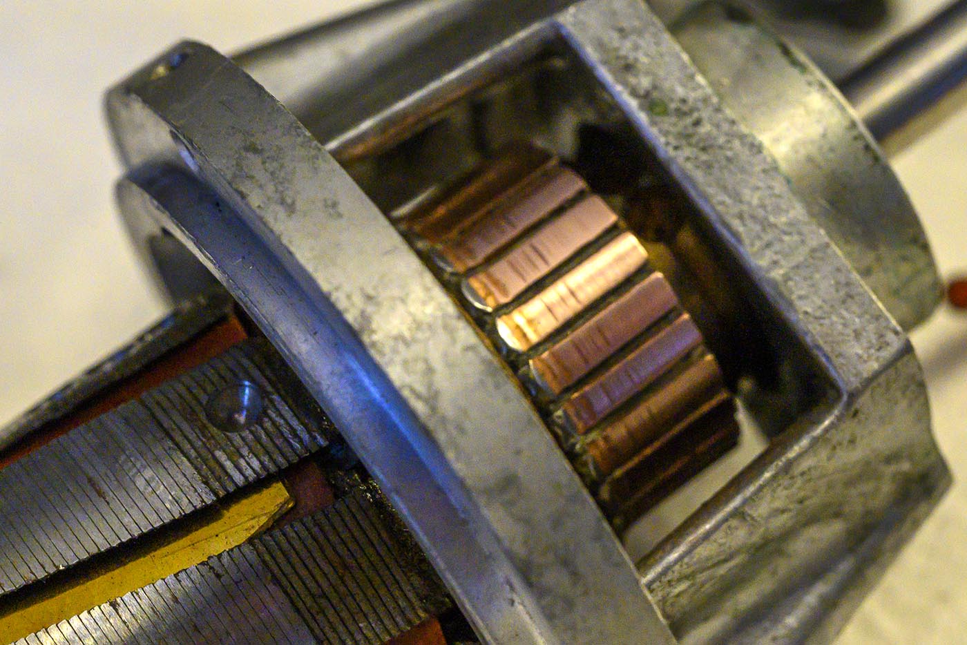
Main motor brushes are really in good shape. Looks like in theory you could unsolder just the carbon brush part and replace them, if such things were available like that.
I can't imagine the complete brush assemblies are available from Arri any more.
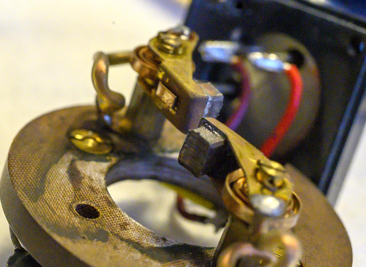
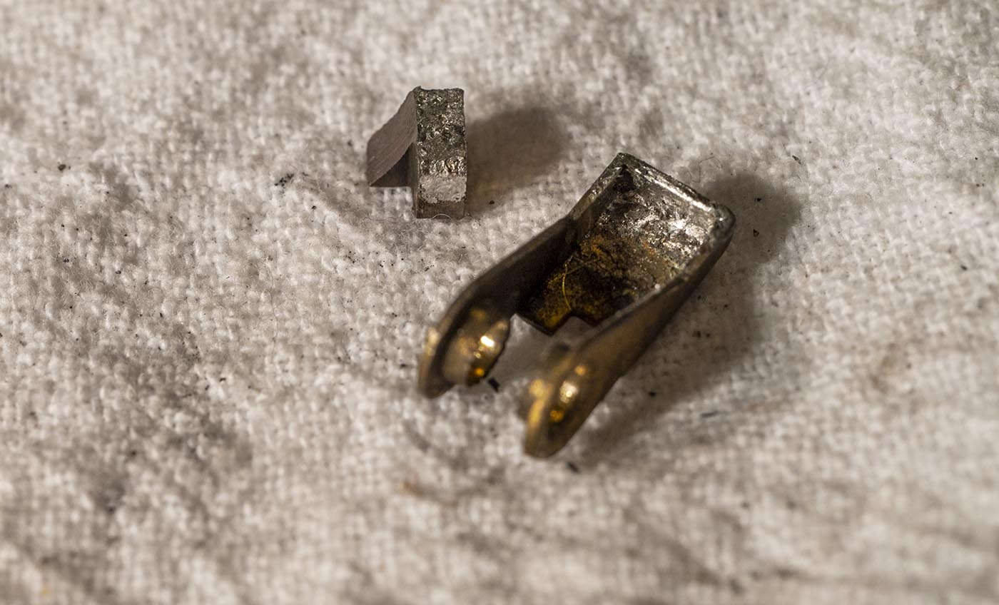
The governor brushes on the other side of the plate are another story. One is significantly more worn than the other, getting on down towards the end of its life.
But that probably means it only has thousands of hours of life left. I'm not going to worry about it ever wearing out under my stewardship.

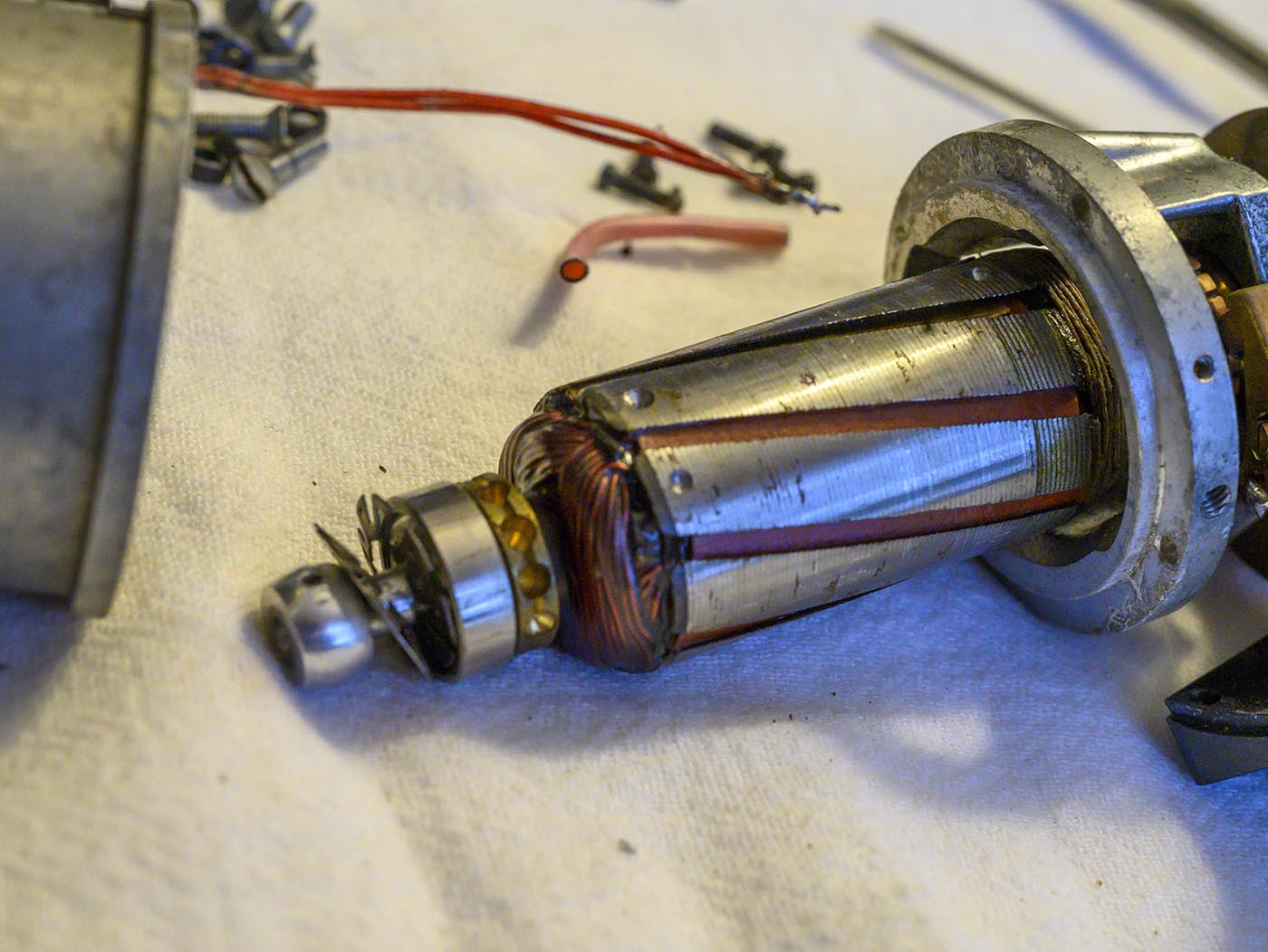
You can see where they drilled away material from the armature to balance it.
Armature contacts are looking much better after some work with some 2000-grit sandpaper. I cleaned and very lightly lubed the spinning contact areas after sanding,
using "instrument grease" as used on old electromechanical pinball machines' sliding electrical contacts.
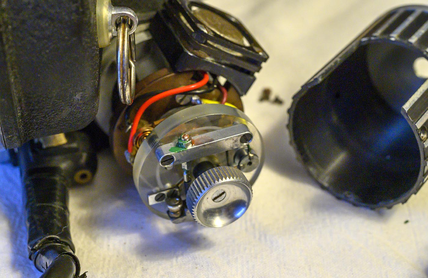
Here is everything all reassembled, but with the cover left off, so I can run it and adjust the speed. If all you need to do is adjust the speed, then all you need
to remove is the 3 screws that hold this cover on, and the one screw that holds the inching knob on, remove both of them, then reattach the knob to hold things together
for testing. When reassembling you will probably need to loosen the two screws holding the transistor to the bakelite plate, and use a bit of "convincing" with
the heel of your hand, to get the cover to slip back under the transistor mounting plate. Then tighten the transistor screws back down again before installing
the three case screws and the knob again.
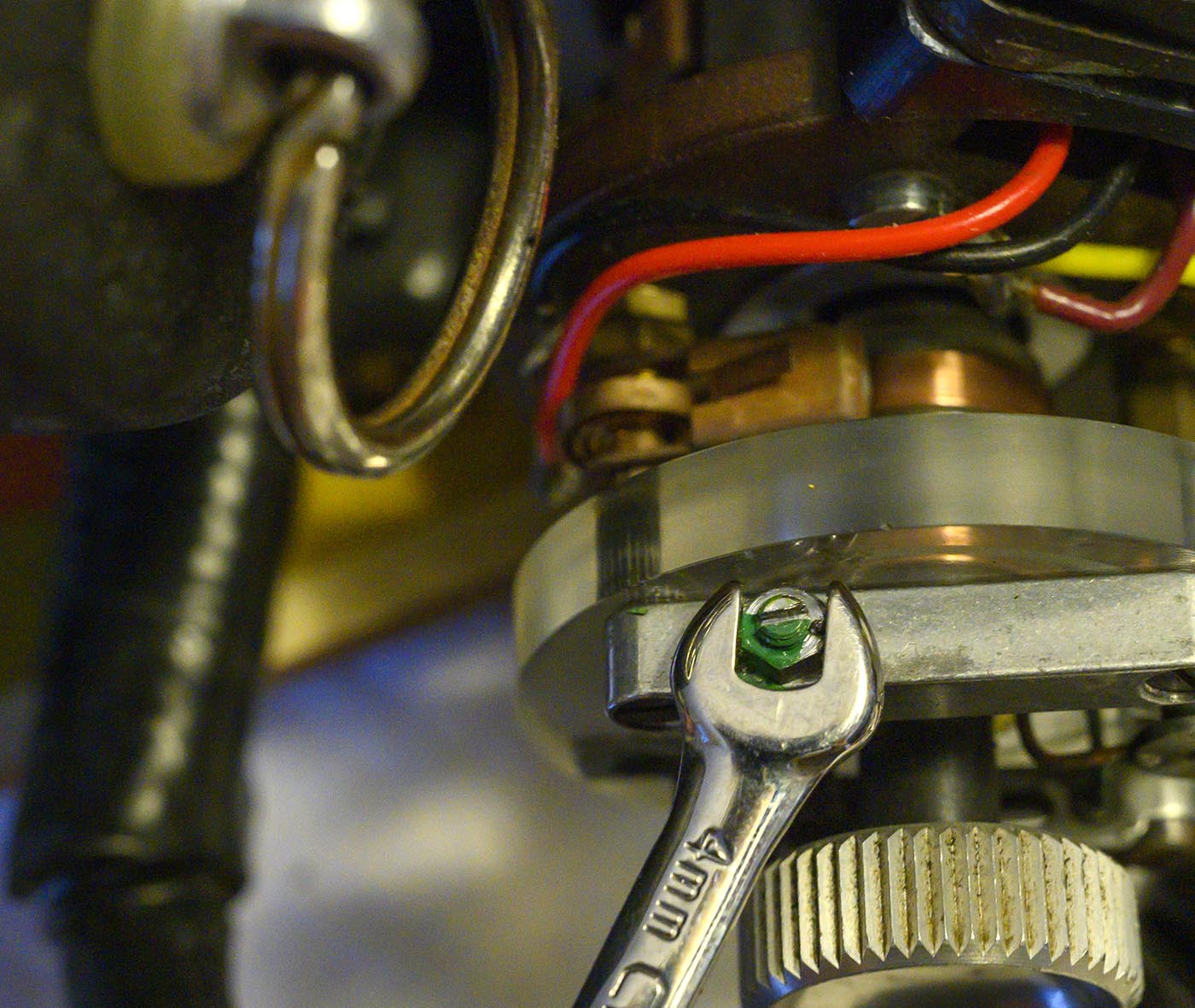
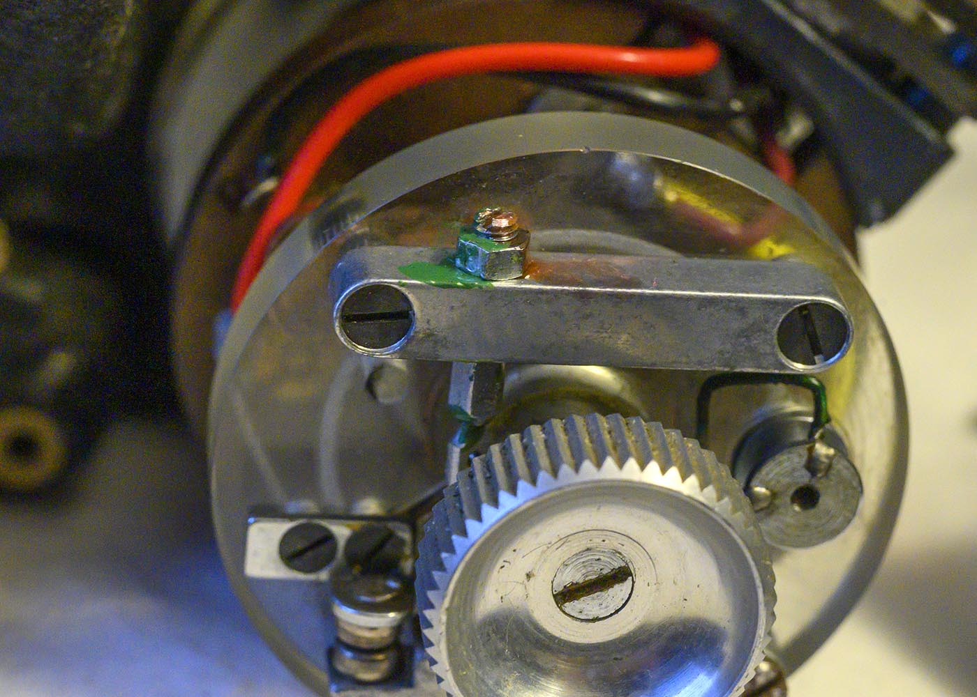
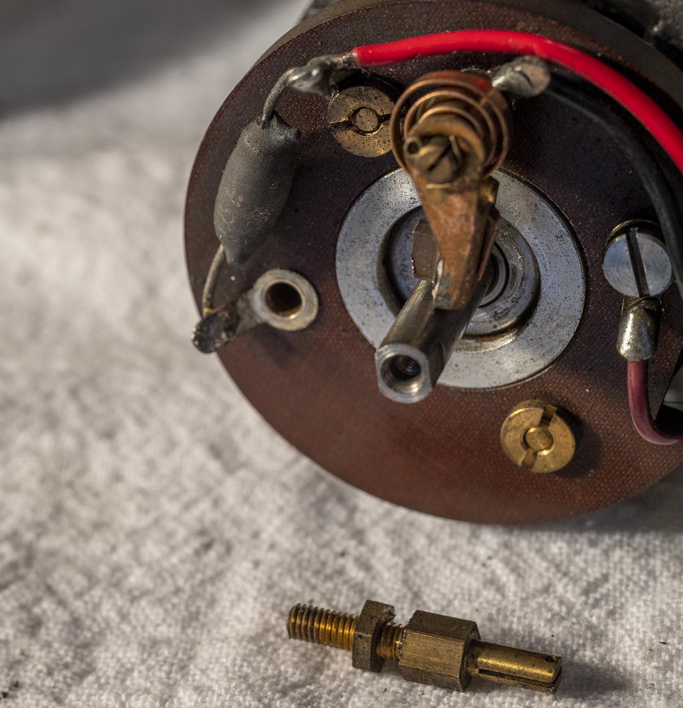
Here is the adjustment screw, and the 4mm wrench you'll need to loosen the locknut to adjust it (along with a small flatblade screwdriver.) If you've ever adjusted
valves on a car engine, you'll be familiar with the annoying way this works: loosen the nut a bit, which will of course move the screw. Move the screw the direction
for speed adjustment, then tighten the locknut again while trying (with a screwdriver) to not let the screw move. Run the camera and check the speed, and repeat
that whole process until you are happy with the speed. Turning the screw COUNTERCLOCKWISE increases the speed. I was just over 1fps slow, and turned the screw
just over a half turn (slot back in the same orientation again) counterclockwise, if that gives you an indication of how much you might need to turn yours.
Results will no doubt vary. I'm betting it slowed down over the years because the spring stretched a little bit, so by screwing the screw out a little bit I
added a bit more tension back to the spring.
Add some paint or exterior threadlocker goo to hold things in place. Remember, this sucker spins quite fast all the time when running, so things could walk loose!
I got a second variable speed motor to do more diabolical experiments on, and imagine my surprise when I opened it up to replace the horrifically noisy worn bearings,
only to discover that it was built slightly differently! The brushes for the governor are mounted 90 degrees apart, instead of 180, and this allows them to use one
of the brush mounting posts as a screw to hold the whole brush mounting assembly on! Well that's a terrible idea, as that means you need to remove a brush entirely
just to get the plate off, so I assume this is an older design.
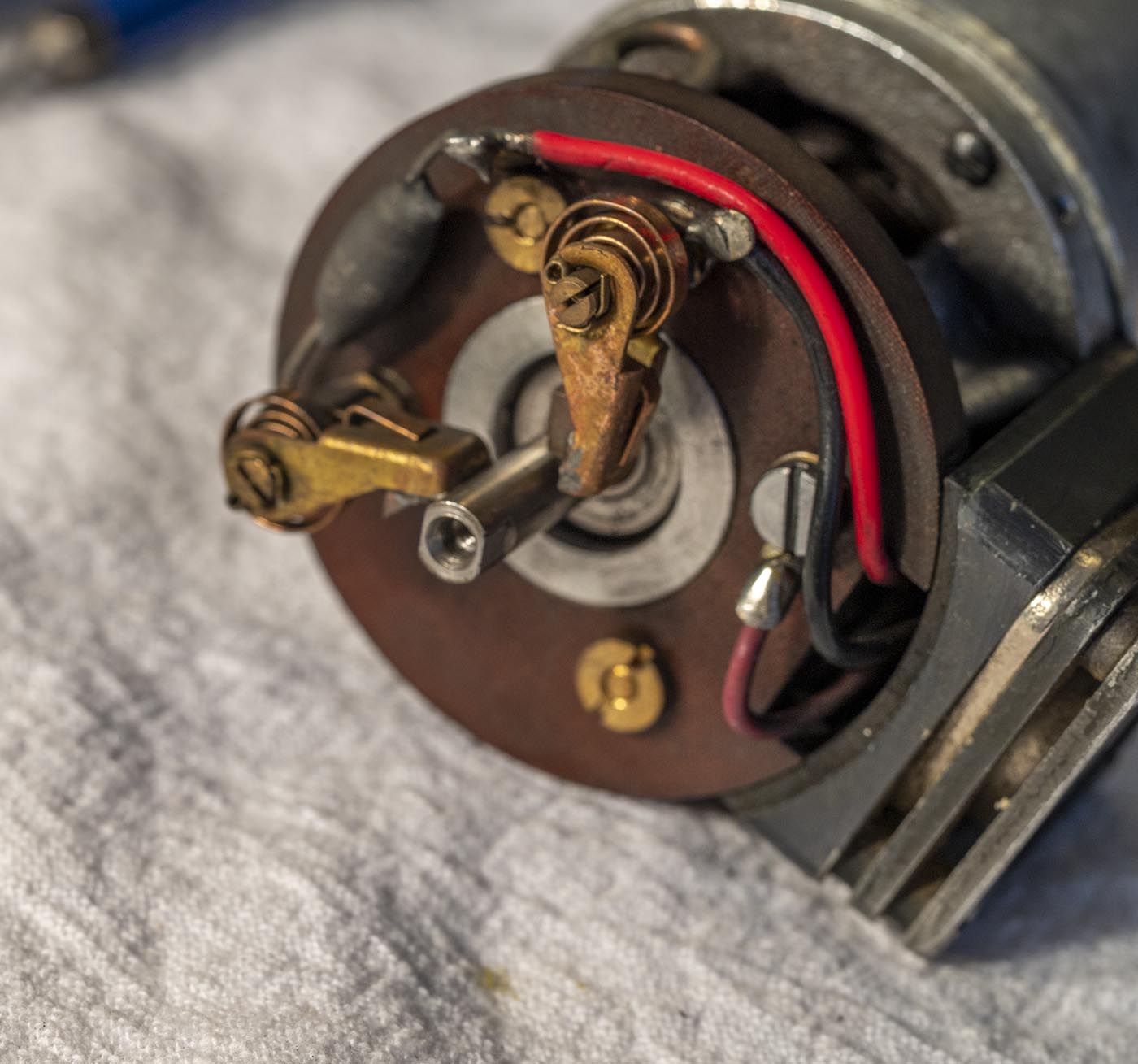
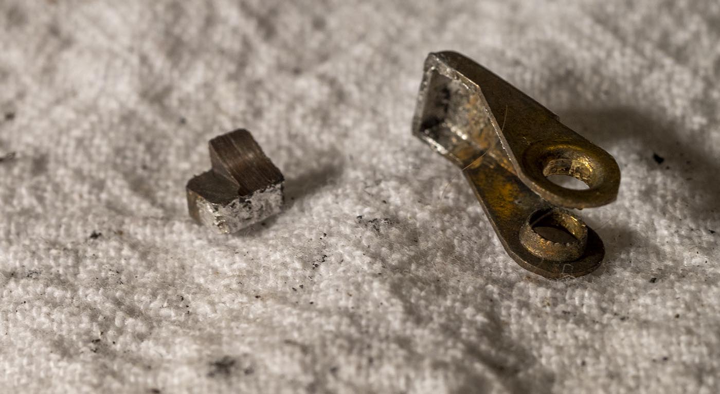
One of the governor bushes was worn so badly that the copper brush holder bracket was just starting to hit the contact ring on the governor - oops! I proved that
the brush carbon blocks are just soldered in, by desoldering that one. I have ordered some more carbon brushes that are oversized and I hope to be able to shape
to fit, and solder them into the brackets.
Yeah, those were some nasty bearings. The motor is all rebuilt with new bearings, quite smooth when turned by hand now, just waiting on the new brush material.
Once it's back together, I'll do some tests to show the range of the speed adjustments, but even with the wrecked bearings I could get under 18fps and over 32fps.